30
Copyright © 2020 Quality Machine Tools, LLC
PM-1228VF v3 2020-10
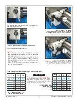
Figure P
Final assembly
(cover attachment hole arrowed)
Figure Q
Cover installed
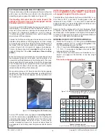
Figure L
Height setting block
Figure M
Indicating the scale side
The dial indicator is clamped to the reading head link plate
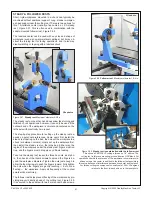
Figure N
Indicating the scale top
skt heads are recommended. For both side and top indi-
cations look for an end-to-end difference of not more than
0.010″.
• Take care to ensure that reading head is exactly aligned with
the scale.
• Connect the ground terminal on the display unit to a reliable
ground on the lathe bed.
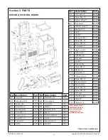
SETTING UP THE DISPLAY
Switch off the display before connecting cables!
•
Plug the cross-slide (X axis) cable into the
upper port
on
the display unit.
•
Plug the longitudinal (Y axis) cable into the
lower port
on
the display unit.
• Switch the display unit ON: then, immediately following the
beep, press the numeral 6 to enter the
Parameter Setup
mode.
• Press the down arrow repeatedly until the word
RESOLUTE
is displayed, then press Enter, ENT (red button).
• Press the blue
X
(cross-slide) button to display
0.001
in the
upper numerical display.
• Press the blue
Zo/Y
(longitudinal) button to display
0.005
in
the lower numerical display.
• Press ENT, then press the down arrow repeatedly until the
word EXIT is displayed. Press ENT again to leave the pa-
rameter setup mode.
The following applies only to the Precision Matthews
brand lathe DRO display.

