


11
PM-1228VF v3 2020-10
Copyright © 2020 Quality Machine Tools, LLC
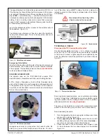
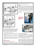
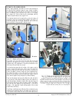
Figure 3-12
Cross-slide and compound dials
Both collars are friction-coupled to their leadscrews by leaf springs. To
zero a dial, or set it to any desired number, hold the handwheel firmly,
then rotate the knurled rim.
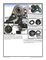
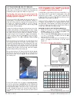
Figure 3-14
Cross-slide and compound gib screws
These are not all the same: Cross-slide, M5 set screws with 8 mm
hex lock nuts; Compound, M6 set screws with 10 mm hex lock nuts
There is no lock screw on the compound.
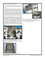
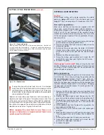
Figure 3-13
Compound base casting - raceway & T-nuts
M6 cross-slide
lock screw
pound to be locked at any desired angle.
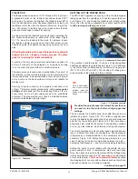
The cross-slide, only, can be locked in place by a socket head
cap screw that clamps the gib against the mating dovetail, Fig-
ure 3-14.
The graduated collars on both cross-slide and compound are
not locked to the leadscrews. They can be set to any reference
value relative to the handwheels. This is especially useful when
making a specific depth of cut in the workpiece. Suppose the
intention is make a 20 thousandths cut in a rotating round bar
... advance the cross-slide slowly, stopping when the tool just
grazes the workpiece; now, holding the handwheel stationary,
rotate the cross slide collar to set ‘0’ against the datum, Figure
3-12; continue to advance the tool to bring ‘20’ to the datum.
Be aware of
leadscrew backlash
when using the dials to
measure distance traveled. Backlash is present (it always is to
some degree) if the cross-slide or compound stays put when
its handwheel is turned a few degrees in the opposite direction.
Lost motion like this can be anything from 5 or 10 thousandths
on the dial, even more. This means that cutting tool motion
must always be in the
same direction
when approaching the
point of reference, then
onward
by a specific amount to the
desired location. Backlash ceases to be an issue - at least on
the cross-slide - if the lathe is equipped with digital readouts
(DROs).