Precision CAM Cowcam Скачать руководство пользователя страница 18


SETTING UP AT THE HOUSE: LCD CONTROLLER SETUP


To set up the PTZ joystick controller with built in LCD monitor, you will need the LCD 
controller, controller power supply, controller antenna, receiver, RCA cable, receiver 
power supply, receiver antenna, and BNC to RCA adapter.


• 

Twist the antenna marked 

for controller

” 

onto the antenna connector on the 

back of the controller, and point the antenna up.


• 

Next, connect the power supply to the power in port on the back of the       
controller and plug it in to a wall power connection.


• 

Place the controller on a stable surface where it will not be exposed to high 
levels of static electricity. 


• 

Twist the antenna marked 

for receiver

” 

on to the gold antenna connector on 

the back of the receiver unit and point it up.


• 

Next, connect one end of the RCA video cable to the audio and video out     
connectors on the back of the receiver.  Normally you can match the colors of 
the connectors, but if your cable does not have a yellow plug, you will have to 
use another one of the connectors in its place such as black.


• 

Now, connect the other end of the RCA cable to the controllers video input 
connector using the BNC to RCA adapter.  Please note the LCD controller does 
not support audio, so you will not need to connect the red or white audio    
cables to it. 


• 

Connect the power supply to the power input on the back of the receiver unit 
and plug it in to a wall power outlet.


• 

Place the receiver on a high surface with the antenna facing the wall that faces 
the barn or camera location 

(see page 33 for more tips on receiver placement).


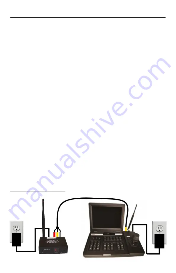
LCD controller setup diagram:


13


Содержание Cowcam

Страница 1: ......

Страница 2: ......

Страница 3: ...house assembly diagram page 5 Standard setup diagram page 6 DVR setup diagram with 4 receivers rear view of DVR page 8 Outdoor receiver setup diagram page 11 Outdoor receiver with DVR setup diagram pa...

Страница 4: ...tup 9 10 11 Setting up at the house Outdoor receiver setup with DVR 12 Setting up at the house LCD controller setup 13 Setting up at the house High gain panel antenna setup 14 Setting up at the barn M...

Страница 5: ...io mod 31 PTZ camera features 32 Troubleshooting Static or poor picture 33 34 Troubleshooting No PTZ control 34 Troubleshooting Camera is dead spinning 35 Troubleshooting Other common problems and sol...

Страница 6: ...e system works and will also allow you to verify everything works and nothing was lost or damaged in transit Should you have any trouble please refer to our online troubleshooting guides and videos on...

Страница 7: ...mera cable black cable with round ends G camera power supply with mounting hardware H transmitter power supply with mounting hardware I PTZ joystick controller with power supply and antenna excluded f...

Страница 8: ...a cable black cable with round ends E transmitter power supply with mounting hardware F receiver with power supply 12 RCA cable antenna and remote excluded from add on kit WHAT COMES WITH THE DVR KIT...

Страница 9: ...erminal block black cable with red and Black wires inside usually about 12 long E receiver power supply with mounting hardware F outdoor receiver video and data adapter splitter A PTZ joystick control...

Страница 10: ...ks and will also allow you to verify everything works and nothing was lost or damaged in transit Below is a quick reference diagram to aid you in assembling the system to test it in the house If you g...

Страница 11: ...ideo input This is sometimes called video1 AV1 or composite Some TVS do not have a dedicated yellow video plug in this case you will need to use the green connector Connect the power supply to the pow...

Страница 12: ...nd plug it into a wall connection Next we will get the receiver or receivers connected to the DVR You will need your receivers power supplies RCA cables antennas and BNC to RCA adapters Twist the ante...

Страница 13: ...SETTING UP AT THE HOUSE DVR SETUP SMART PHONE OPTION 8 Rear view of DVR To see how to set up the DVR to work on your smartphone go to page 30 DVR setup diagram with 4 receivers...

Страница 14: ...irectly below the eaves trough or roof line as this will expose the receiver to more water and ice which may hinder its performance To set up your outdoor receiver you will need the outdoor receiver r...

Страница 15: ...on the bottom of the outdoor receiver Run the video cable into the house to your TV location from where you wish to view the camera Connect the receiver power cable to the matching connector on the o...

Страница 16: ...oor receiver adapter using the supplied terminal block Red wire to green wire black wire to blue wire Connect the other end of the controller cable to the back of the joystick controller using the gre...

Страница 17: ...ystick controller you will connect it to the A B ports on the DVR You will not need to use a data box for this type of setup When connecting the controller cable to the back of the DVR the red wire go...

Страница 18: ...nnector on the back of the receiver unit and point it up Next connect one end of the RCA video cable to the audio and video out connectors on the back of the receiver Normally you can match the colors...

Страница 19: ...the barn You can mount it using 2 standard wood screws or with the supplied pole mounting kit Pay attention to the direction of the H and V arrows to en sure the correct orientation of the antenna The...

Страница 20: ...stallation make sure you will be able secure the camera mount directly to a stud or into a solid pole If this is not possible we recommend reinforcing with 3 4 plywood or better Your mounting kit incl...

Страница 21: ...You can also install the camera without using the mount by using the lag bolts and the cameras existing mounting holes if you prefer Now connect the camera cable and camera power cable to the matchin...

Страница 22: ...don t recommend mounting it directly below the eaves trough or roof line as this will expose the transmitter to more water and ice which may hinder its performance To mount the transmitter you will ne...

Страница 23: ...matching connector on the transmitter and run the cable towards the power connection Mount the transmitter power supply near the power connection using the supplied mounting screws and connect the tra...

Страница 24: ...ng up a normal transmitter the only difference is you will be connecting 2 cameras to it instead of just one Dual transmitters also require a different power supply box than the standard transmitter T...

Страница 25: ...ide of the audio mod box SETTING UP AT THE BARN HIGH GAIN PANEL ANTENNA SETUP Setting up the high gain panel antenna at the barn is the same process as setting it up at the house The only difference i...

Страница 26: ...amera will most likely be set to If you have more than one cam era you can determine what channel each camera is on by looking at the sticker on the bottom of the transmitter for that camera Once you...

Страница 27: ...you can use the IR remote to switch between channels Remote layout diagram Advanced receiver functions The receiver also has some advanced functions The next couple of pages walk you through how to co...

Страница 28: ...ss E key to enter the programming mode the display will start flashing 3 use the up and down arrow keys to select the channel you wish to delete 4 press the RECALL key 5 use the left arrow key set the...

Страница 29: ...he up and down arrows to find the channel you want configure 4 press the RECALL key 5 use the right arrow key to set the number of seconds you want that channel to show for If you set the display time...

Страница 30: ...this display tells you what camera you are currently set to This screen also displays the parameters of the controller B Joystick this is the main control interface for your camera You can control th...

Страница 31: ...t Cam ID your cameras are set to you can find out by looking for the ID sticker on the camera itself You can also control several pre set functions of the camera using the functions keys For example t...

Страница 32: ...r changing the camera you are controlling as well as entering numbers to run different pre set functions B LCD display this screen will display your camera It also displays the parameters of the contr...

Страница 33: ...r off unit The basics When you first power up your DVR you may see the admin security and start up wizard you can just click cancel for both To log into the DVR use the user name user and the password...

Страница 34: ...your pc and open it up Run the application on the USB stick called play Click the small arrow icon on the far left side of the tool bar and browse through your files until you get to the USB stick Cli...

Страница 35: ...If you have an Android phone Download an App called GDMSS LITE and launch it Click the camera icon in the upper right corner of the screen Click the plus button to make a new connection Click P2P the...

Страница 36: ...nnel 2 The channel the receiver changes to will always be the same as the Cam ID up to 7 The outdoor receiver does not have any advanced functions like the standard receiver When using the outdoor rec...

Страница 37: ...om is the amount of mechanical zoom range on the cameras lens Digital zoom The 26X cameras have extra zoom capability called digital zoom This extra zoom is achieved by stretching the picture This wor...

Страница 38: ...ill weaken your signal are trees metal structures land formations brick stucco siding foil insulation Low E windows metal siding hay bales vehicles and going through too many walls There are a few thi...

Страница 39: ...screen on your TV ex 001 There is also a sticker on the camera that indicates the camera ID You can also find the camera ID by restarting the camera and watching the TV screen while the camera does i...

Страница 40: ...ion or follow the trou bleshooting flowcharts at the back of the book TROUBLESHOOTING OTHER COMMON PROBLEMS AND SOLUTIONS Hard reset Many issues can be fixed by simply unplugging everything at the hou...

Страница 41: ...36 TROUBLESHOOTING FLOW CHART NO PTZ CONTROL...

Страница 42: ...37 TROUBLESHOOTING FLOW CHART NO PICTURE...

Страница 43: ...38 TROUBLESHOOTING FLOW POOR PICTURE...

Страница 44: ...pikes surges poor quality power improper grounding static discharge or black outs Damage caused by improper installation or use of product Damage caused by shipping companies or as a result of inadequ...

Страница 45: ...equipment will be held until all equipment is returned and confirmed to be in the same condition as it was when it left our shop If any damage to loaner equipment is found the cost to repair said dama...

Страница 46: ...________________ ___________________________________________________________ ___________________________________________________________ ___________________________________________________________ ___...

Страница 47: ......

Страница 48: ...Ltd 545 Assiniboine Ave Brandon MB R7A 0G3 Tel 204 728 8878 Toll Free 1 866 289 8164 Fax 204 725 2234 Email info allenleigh ca Web www allenleigh ca Facebook AllenLeighSC Twitter AllenLeighSC YouTube...

Отзывы: