


O
UTDOOR ENCLOSURE TYPE
MINI
HANDBOOK
17
LNB Voltage tolerance
The LNB voltage presented at the RF ports is nominally per the setting, but manufacturing variances have the
potential for the following.
LNB Voltage
setting
Minimum Maximum
13
12.6
13.5
15
14.6
15.6
18
17.5
18.8
24
23.3
25.0
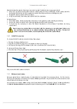
WARNING:
When connecting any equipment to the RF ports that isn’t capable of handling the
LNB voltage, ensure a DC block is used to protect it.
2.10
High voltage or high power LNB/BUC supply options
When the on-board variable supply is not suitable for an application, the option for using a dedicated PSU can
be considered.
Power supply redundancy for the ODE-MINI is then no longer possible, but the option for 12V or 48V at up to
15 W is possible or even 25 W for temperature environments < 45 Degrees Centigrade.
Please consult with the factory for this arrangement as it will be built to order and there are no customer re-
configurable options.
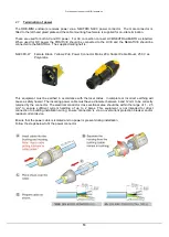
2.11
ODE-MINI power supplies
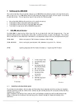
The ODE-MINI is equipped with internal power supply modules. They are generally used in a dual redundant
configuration with identical modules in the left hand (LH) and right hand (RH) positions. It can optionally be
equipped with either just a single main PSU module (LH) or with a main PSU (LH) and LNA/BUC PSU (RH).
The voltage inputs for the various power supplies
’ options have the following requirements.
AC input wide range
88
– 264 VAC 47-63 Hz
Power supply: LPS-MINI
DC input
18-75 VDC
Power supply: LPS-MINI-DC
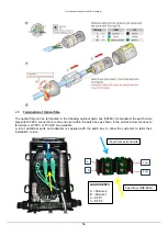
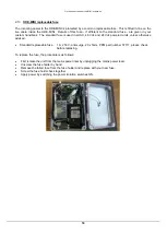
2.12
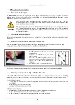
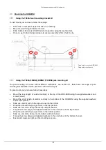
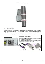
Replacement of Power Supply Modules
The outdoor housing can be fitted with either one or two power supply modules, the latter provides dual
redundant power supply protection for the housing. The power supplies come pre-installed in the outdoor
housing. Should it be necessary to replace a power supply module, the procedure is as follows:
First isolate the unit from the mains power inlet by switching the power isolation switch adjacent to the
unit OFF.
Disconnect the electrical connections between the power supply module and the switch bar.
Undo the two nuts holding the power supply unit in place. Retain the nuts to refit the new power supply.
Locate the new module on the studs on the rear plate. Replace the nuts to hold the power supply
module in place.
Reconnect the electrical connector between the power supply module and the switch bar.
Apply power by switching the power isolation switch ON.


