


O
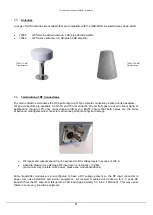
UTDOOR ENCLOSURE TYPE
MINI
HANDBOOK
15
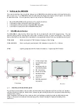
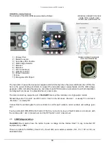
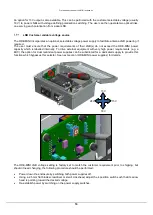
ODE-MINI, internal features
The internals of the ODE-MINI are presented as follows:
The top section houses the dual power supplies which sit directly above the power distribution bar. Within this
bar are the power sharing electronics to support the redundant power supply feature and the LNB voltage
generator. LEDs indicating the presence and state of each PSU module are presented to aid both installation
and diagnostic processes. A replaceable fuse is present also.
The main module bay, supports up to 2
ViaLiteHD
blue or yellow modules or a single purple module.
Standard layout is TX in slot 1 and RX in slot 2. Item 5 in the list above - Module 1 - is usually TX, and item 6
- Module 2
– is usually RX.
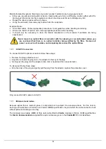
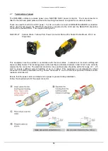
Connect RJ45 and interrogate the site controller to confirm part numbers, serial numbers and settings (gain
etc.).
If using a standard ODE-MINI at both ends of the link, you must ensure your Neutrik cable is a crossover, with
the module ports 1 and 2 crossed over and the SFP ports 1 and 2 crossed over.
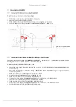
2.9
LNB Voltage selection
ViaLiteHD
Blue modules have the option to pass a voltage via the internal bias T to any connected RF
equipment (e.g. LNBs).
There are options for (NONE), (Fixed 12V), (Fixed 48V) and customer variable (13V, 15V, 18V or 24V) as
illustrated below.
1
2
3
4
5
6
7
8
9
1) Primary PSU
2) Media Converter
3) Secondary PSU Position
4) LNB Voltage Selector
5) Module 1
6) Module 2
7) RF Connection(s)
8) Optical connector
9) Power Connector
10) Fuse
11) Management RJ45 port
10
11
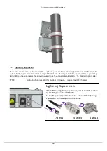
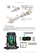
P1
P2
INTERNAL CONNECTION VIEW
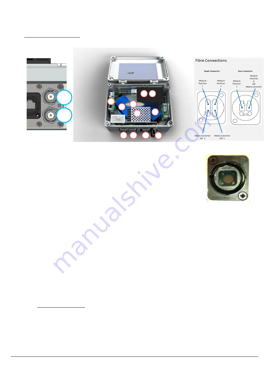
FIBRE TYPE: LC/APC ONLY
REAR VIEW SHOWN BELOW
FIBRE CONNECTOR FRONT
VIEW SHOWN BELOW


