3
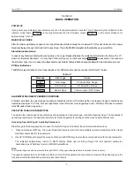
BASIC OPERATION
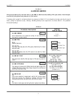
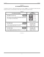
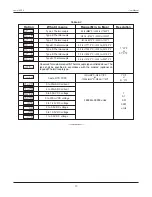
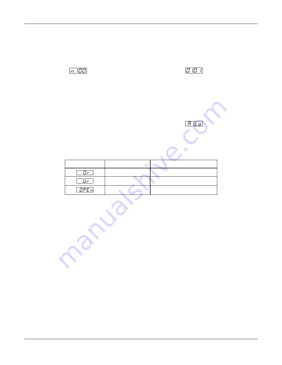
Table 2.1
PV above Max. Range
PV below Min. Range
Message
Error Type
Cause
Thermocouple / RTD broken
Sensor Open
Under-range
Over-range
ALARM STATUS UNDER PV ERROR CONDITIONS
For Alarm activation, the under-range condition is treated as minimum PV, whereas the over-range and open conditions are
treated as maximum PV. Thus, Process High Alarm turns ON under
Over-range/Open error
. Similarly, Process Low Alarm
turns ON under
Under-range error
.
OPERATOR PAGE AND PARAMETERS
The parameters that require frequent settings are organized on a separate page, called the Operator Page. The availability of
operator parameters is controlled at supervisory level and the parameter setting cannot be locked by the Master Lock.
Accessing Operator Page & Adjusting Parameters
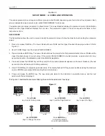
Step through the following sequence to open the Operator Page and to adjust the operator parameter values.
1. Press and release ‘OPR’ key. The Lower Readout shows prompt for the first available operator parameter and the Upper
Readout shows value for the parameter.
2. Use UP / DOWN keys to adjust the value and then press ENTER key to store the set value and scroll to the next parameter.
The
automatically reverts to MAIN Display Mode upon scrolling through the last operator parameter.
indicator
Alternatively, use PAGE key to return to MAIN Display Mode.
Note:
The Operator Page can also be accessed through PAGE-0. (The pages and parameters are explained in next section).
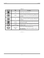
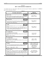
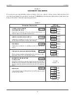
The operator parameters are described in Table 2.2. Note that the parameters presented on Operator Page depend upon the
functions selected/enabled and supervisory level permissions.
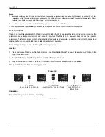
POWER-UP
Upon power-up, all displays and indicators are lit on for approximately 3 seconds. This is followed by the indication of the
indicator model name on the Upper Readout and the firmware version on the Lower Readout, for
approximately 1 second.
MAIN DISPLAY MODE
After the Power-up display sequence, the Upper Readout starts showing the measured PV (Process Value) and the Lower
Readout displays the user set Units for Process Value. This is the MAIN Display Mode that shall be used most often.
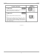
Alarm Status Information
In case of any Alarm (or Alarms) becoming active, the Lower Readout flashes the related Alarm details in the format ‘Ax.YY’,
where x is the Alarm Number (1, 2, 3 or 4) and YY is Alarm Type (Lo or Hi) For example means Alarm-1 is active and
the set Alarm Type is Low. In case of multiple Alarms, each Alarm Status is flashed sequentially with 3 Seconds time interval.
PV Error Indications
The
PV
Error type is flashed on the Upper Readout. For different errors and the causes, refer Table 2.1 below.
User Manual
neuro 100EX
Section 2


