PPA DZ 1500 Скачать руководство пользователя страница 5

5

4 - IMPORTANT SAFETY INSTRUCTIONS
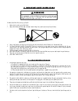
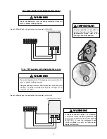
WARNING

This equipment is to be installed and serviced by a professional gate 

operator technician only. It is important that the specialized installer 

follow all instructions given in this manual.

To Reduce the Risk of Severe Injury or Death:

1.  READ AND FOLLOW ALL INSTRUCTIONS

2.  Never let children operate or play with door controls. Keep the remote control away from children.

3.  Always keep people and objects away from the gate. NO ONE SHOULD CROSS THE PATH OF THE MOVING GATE.

4.  Test the gate operator monthly. The gate MUST reverse on contact with a rigid object or stop when an object activates the non-

contact sensors. After adjusting the force or the limit of travel, retest the gate operator. Failure to adjust and retest the gate operator 

properly can increase the risk of injury or death.

5.  Use the emergency release only when the gate is not moving.

6.  KEEP GATES PROPERLY MAINTAINED. Read the owner’s manual. Have a qualified service person make repairs to gate hardware.

7.  The entrance is for vehicles only. Pedestrians must use separate entrance. 

8.  SAVE THESE INSTRUCTIONS.


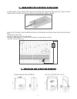
4.1 – Safety Installation Information

1.  Install the gate operator only when:

a) The operator is appropriate for the construction and the usage class of the gate.

b) All openings of a horizontal slide gate are guarded or screened from the bottom of the gate to a minimum of 6’ (1.83 m) 

above the ground to prevent a 2 ¼” (6cm) diameter sphere from passing through the openings anywhere in the gate, and in 

that portion of the adjacent fence that the gate covers in the open position.

c) All exposed pinch points are eliminated or guarded, and guarding is supplied for exposed rollers

2.  The operator is intended for installation only on gates used for vehicles. Pedestrians must be supplied with a separate access 

opening. The pedestrian access opening shall be designed to promote pedestrian usage. Locate the gate such that persons will 

not come in contact with the vehicular gate during the entire path of travel of the vehicular gate.

3.  The gate must be installed in a location so that enough clearance is supplied between the gate and adjacent structures when 

opening and closing to reduce the risk of entrapment. Swinging gates shall not be open into public access areas.

4.  The gate must be properly installed and work freely in both directions prior to the installation of the gate operator

5.  Controls intended for user activation must be located at least six feet (6’) away from any moving part of the gate and where the 

user is prevented from reaching over, under, around or through the gate to operate the controls. Outdoor or easily accessible 

controls shall have a security feature to prevent unauthorized use.

6.  The Reset switch must be located in the line-of-sight of the gate. Activation of the reset control shall not cause the operator to 

start.

Содержание DZ 1500

Страница 1: ...DZ PREDIAL DZ CONDOMINIUM DZ 1500 Technical Manual...

Страница 2: ......

Страница 3: ...nnection 19 14 FORCE ADJUSTMENT 19 14 1 FOP High Speed Force Adjustment 19 14 2 FME Low Speed Force Adjustment 20 15 GATE SYSTEM LOGIC FUNCTION 20 15 1 First operation after a frequency inverter is in...

Страница 4: ...ther restricted access locations not servicing the general public in which unauthorized access is prevented via supervision by security personnel 2 SAFETY ACCESSORY SELECTION All UL325 PPA compliant g...

Страница 5: ...r screened from the bottom of the gate to a minimum of 6 1 83 m above the ground to prevent a 2 6cm diameter sphere from passing through the openings anywhere in the gate and in that portion of the ad...

Страница 6: ...obstruction A wireless contact sensor shall function under the intended end use conditions d One or more contact sensors shall be located on the inside and outside leading edge of a swing gate Additio...

Страница 7: ...breaker in the electrical panel is in the OFF position before proceeding with the installation A separated power disconnect switch may be needed in your area Check your local building codes before in...

Страница 8: ...ter must be installed between the power distribution box and the total disconnect device inside the concrete base Install conduits for the 120 Vac Main power supply MUST run in separated conduits The...

Страница 9: ...vide a concrete pad following the guidelines below Step 2 The dimensions of the concrete pad shall be appropriate for the operator dimensions The concrete pad shall be at a distance of approximately 0...

Страница 10: ...ning of the aligned operator to the gate and enter the anchor bolts x 4 without tightening them Move the gate check if it does not touch the operator over the course If this occurs back off the operat...

Страница 11: ...te leaf this warped provide shims to ensure alignment of the rack In some cases that the rack must pass the length of the sheet In this case it provides a clamps so do not skip teeth in starting the m...

Страница 12: ...t of the operator REED This magnet will trigger the open limit switch Step 3 Trigger the engine and see if the REED s are off properly If necessary reverse the board connector After the brackets set o...

Страница 13: ...hich stores the acquired remote controls codes in a encripted way This memory can be removed to be used in another compatible PPA product such as PPA s loose receiver Alcance and vice versa The contro...

Страница 14: ...nection The three wires of the induction motor must be connected to the MOTOR terminal block THERE IS NO NEED TO FOLLOW THE WIRES COLOR SEQUENCE3 12 4 ENC encoder connection It is used to connect thro...

Страница 15: ...vated The HRF Jumper must be removed when the separated receptor is added to the system to switch off the incorporated receptor 12 8 BOT pushbutton connection The control board acknowledges a pushbutt...

Страница 16: ...ntered the operator will reverse for 2 seconds and hold the gate at this position and disable if enabled the auto close function 2 1 If the operator encounters another obstruction twice consecutively...

Страница 17: ...ovement does not generate any entrapment situation it is possible to disable the input for the open sensor see topic 16 3 TRV Use only Miller Edge 4 wire pulsed sensors to comply with UL325 IMPORTANT...

Страница 18: ...properly aligned The red light at the top of the photocell will be off whenever the photocell is aligned and unobstructed and is on whenever something is between the photocell and the reflector TRIFL...

Страница 19: ...the safety reversal system MUST be tested Gate MUST reverse on contact with a rigid object 14 1 FOP High Speed Force Adjustment Before starting the adjustment of the operating force the operator must...

Страница 20: ...gate should start opening Afterwards let the gate open until it reaches the opening physical stop or the REED A magnet limit switch is activated Then it will automatically reverse the movement directi...

Страница 21: ...given point of its travel to set limits or to verify the mechanical part In this mode pressing the button starts the motor clockwise rotation while the button is pressed and when the button is pressed...

Страница 22: ...lowed is 240 seconds Led OSC ON FCF Switches 1 and 3 Closed end of stroke Increases or decreases the distance in which the operator starts to slow down when closing FCA Switches 1 and 4 Open end of st...

Страница 23: ...quiring process begins VFC Switch 3 Speed at the travel s limits Speed adjustment for starting and stopping region Dip 3 to ON VFC Button increases the speed Button decreases the speed In gates the ad...

Страница 24: ...two seconds Afterwards press the button of the TriFlex control board Observe that before the transmitter has been added the OSC LED blinked rapidly after the addition process OSC LED keeps lit during...

Страница 25: ...ate The lithium battery should produce power for up to 1 year To replace battery remove the clip use the philips screwdriver to remove the screw FIGO controller doesn t have screws and open the case a...

Страница 26: ...e the 1 switch of the DS1 DIP switch to the ON position press both and buttons of the control board at the same time for 10 seconds observe that the OSC blinks once per second and after the 10 second...

Страница 27: ...gate leaf 4 To operate again in automatic mode return the lever to the starting position and turn the key clockwise 23 ACCESSORIES The electronic control unit allows the installation of other accessor...

Страница 28: ...rapidly blinks in 0 1 second intervals to warn that the capacitors have been disarmed due to over current or short circuit on the motor The board can normally run 10 seconds after the over current 24...

Страница 29: ...shutdown mode Audio alarm will sound and the operator will need to be reset For more information see topic 13 5 25 MAINTENANCE On the table below are cited some PROBLEMS FAULTS POSSIBLE CAUSES AND COR...

Страница 30: ...30 26 REPAIR PARTS DZ PREDIAL JET FLEX 60HZ U...

Страница 31: ...31...

Страница 32: ...32 DZ CONDOMINIUM JET FLEX 60HZ U...

Страница 33: ...33...

Страница 34: ...34 DZ 1500 JET FLEX 60HZ Z12 U...

Страница 35: ...35...

Страница 36: ...MOTOPPAR IND STRIA E COM RCIO DE AUTOMATIZADORES LTDA Av Dr Labieno da Costa Machado 3526 Distrito Industrial CEP 17400 000 Gar a SP Brazil www ppa com br...

Отзывы: