


22
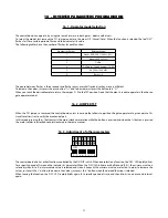
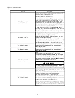
Programming functions chart:
Function
Description
“_” or “TX (Switch #1)
Function selector. It selects the underlined functions and selects the
function to add and erase transmitters (TX).
Function: Add and erase transmitters (TX)
1 – Add: When this only switch is on 'ON" position, the control board
is ready to add or erase transmitters (TX). In order to add a TX, press
the transmitter button after activating the aforementioned switch.
Observe that the 'OSC' LED blinks rapidly if it is receivng a signal. Press
'+' button of the board to add it. Observe that the 'OSC' LED keeps lit
when the board receives a signal already added.
2 – Erase: In order to erase the transmitters added to the memory,
press both '-' and '+' button at the same time for 10 seconds; observe
that the LED will blink once per second; afer the 10-second period is
over, all transmitters have been erased from the memory.
“SA” (Switches #1 and #2)
Push-to-close function / Pause time on auto-close mode.
Press “+” button for incrementing the pause time.
Press “-“ button for decrementing the pause time.
Each button pressed increment or decrement the pause time from 2
seconds (1 seconds if in barrier mode).
After the pause time, the operator will close automatically.
To disable the auto-close function, set the pause time to zero (Led OSC
blinking).
The maximum pause time allowed is 240 seconds (Led OSC ON).
“FCF” (Switches #1 and #3)
Closed end-of-stroke.
Increases or decreases the distance in which the operator starts to
slow down when closing.
“FCA” (Switches #1 and #4)
Open end-of-stroke.
Increases or decreases the distance in which the operator starts to
slow down when opening.
“FOL” (Switches #1 and #5)
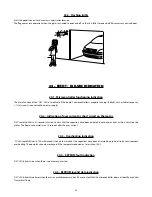
Gates:
HOW TO ADJUST THE GAP BETWEEN THE GATE AND ITS STOP.
If necessary, one can adjust the gap between the stop and the gate
when th operator stops its opening / closing cycle. One can make it
closer or more distant from the stop.
The minimum level is 0 (LED blinking); it increases and decreases one
level at a time up to its maximum 10 level (LED lit).
IMPORTANT
To test the changes, it is necessary to activate the gate operator
once so that it performs an opening / closing cycle.
“FME” (Switches #1 and #6)
HOW TO DECREASE OR INCREASE THE FORCE OF THE MOTOR DURING
TRAVEL RECOGNITION.
If necessary, it is possible to decrease the motor force during the travel
recognition, for example, to avoid that the rack bar breaks.
You can also increase the strength, in case it is necessary.
Press '+' button to increase the strength and the '-' button to decrease
it.
The minimum level is 40% (LED blinking) and it increases four levels at
a time (4%) up to the maximum 100% level (LED lit).
This is the same force that will be used in the limits of the gate travel
(“Low Speed Force”). This is a very important configuration because it
is related to entrapment protection adjustment. For more information
see topic ‘14.2’
Содержание DZ 1500
Страница 1: ...DZ PREDIAL DZ CONDOMINIUM DZ 1500 Technical Manual...
Страница 2: ......
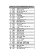
Страница 30: ...30 26 REPAIR PARTS DZ PREDIAL JET FLEX 60HZ U...
Страница 31: ...31...
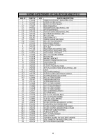
Страница 32: ...32 DZ CONDOMINIUM JET FLEX 60HZ U...
Страница 33: ...33...
Страница 34: ...34 DZ 1500 JET FLEX 60HZ Z12 U...
Страница 35: ...35...


