background image

Содержание PowerEgg

Страница 1: ...PowerEgg User Manual PEGF E1 0 PowerVision ...

Страница 2: ...ircraft 9 Flight Modes 9 Accessibility 10 Aircraft Status lndicator 14 Description of Aircraft Status lndicator 15 Visual Positioning System 16 Propellers 18 Intelligent Battery 18 Remote Controller 23 Overview of Standard Controller 23 Operation of Standard Controller 24 Standard Controller Turn On Off 24 Standard Controller Charge 25 Standard Controller Control 25 Standard Remote Controller lndi...

Страница 3: ...n On Off 33 Connection 33 Frequency Match of Base Station 34 Unbind 35 Charge 36 Indicator 36 Gimbal Camera 37 Overview of Gimbal Camera 37 Gimbal Usage 37 Introduction to Vision 38 Product Description 38 Vision Features 38 Homepage 38 Display of Relevant Parameters 40 One click Return Home 41 Route Planning 41 Flight Modes 42 Return Point Settings 42 Electronic Fencing 43 Positioning 43 ...

Страница 4: ...ooting 44 Settings 44 Media 47 Service 47 Flight 48 Flight Restrictions and Special Area Limited Flight 48 Flight Environment Requirements 49 Connection of Aircraft Remote Controller and Vision 49 Compass Calibration 52 Start Stop The Motor 54 Emergency Stop 54 Basic Flight 56 ...

Страница 5: ...al time manner via Vision and take photos and video I Feature Highlights 1 Unique egg shape design and perfect combination of technology and art 2 No dismantling required integrated design foldable and easy to carry 3 Operated by an innovative gesture based remote controller which enables the user to get started in one minute 4 Flight safety built in 5 360 panoramic shooting with integrated 4K UHD...

Страница 6: ... 0ptical positioning sensors and ultr asonic positioning system 4 Aircraft front LED indicator 5 Aircraft Status LED indicator 6 Brishless low friction motor pods 7 Propellers 8 Power switch Landing gear control Frequency button 9 Battery compartment access button 02 ...

Страница 7: ...t to base station 12 Power Switch 1 Mode switch 2 Left joystick 3 Right joystick 4 Custom button 5 Take off land stop landing 6 Status battery indicator 7 Return to home Cancel 13 Left top button gimbal back to position with short press selfie with double press gimbal face downward with long press 14 Left finger wheel gimbal pitch 03 ...

Страница 8: ...or 00 2 Joystick gimbal control 3 Custom button I 4 Ascend button 5 Descend button 6 Take off land stop landing Return to home cancel 8 Take photos videos 9 Gesture activation 10 Power switch g ff DD 11 Port connect to base station 12 Micro USB charging port 04 ...

Страница 9: ...icator 2 lmage transmitting signal indicator 3 Power switch 4 Cell phone connection bracket 5 Tablet connection bracket 6 USB port 7 Port connect to the controller 8 Micro USB charging port L 1 L ooocffi I CT 71 1 Ii 0 How to use bracket is presented in the graph 05 ...

Страница 10: ...attery into the chamber You ll hear a clicking sound when the battery fits in the chamber and gets locked Note When replacing the battery while the landing gear is deployed do not insert the battery without first lifting and holding the aircraft Not doing so may result in your device being damaged 3 Take off the lower cover Note The lower cover must be removed before the unit is powered on otherwi...

Страница 11: ...cator of the aircraft is on I 5 Spread the propellers of the aircraft with both hands 6 Place the aircraft on the ground surface at least 1Om from the pilot with the head of the aircraft indicated by the red lights on the arms facing the flying direction and pilot facing the tail the power button also indicates the front of the aircraft Head direction Radius of safety 10m 07 ...

Страница 12: ...esture based remote controller with a data cable t Connect the data cable to this port Connect the data cable to this port If the standard remote controller is used for flight control connect the base station to the bracket of the standard remote controller and connect them through cable Connect through this port Connect through this port 08 ...

Страница 13: ...strength If GPS is unavailable the visual positioning system and sonar are used to ensure accurate hovering of the aircraft including indoors When neither GPS signals nor the visual positioning system satisfies the condition for proper and safe flight the system will automatically switch to Professional Mode In this case only sonar is provided E Mode Easy Control Super easy flight mode In this mod...

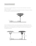
Страница 14: ...he automatic take off button on the remote controller until it vibrates The aircraft ascends to a height of 1 3m above the ground at a set speed and then automatically hovers in the air Automatic landing Long press the automatic landing button until it vibrates The aircraft starts to descend at a set speed from the current position subject to horizontal control during descending Smart return to ho...

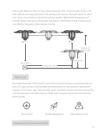
Страница 15: ... I Return point Less than 1Om 1 2 lf the aircraft flies higher than the return altitude default value 20m beyond 2 10m it first makes a turn to face its head towards the operator flies to the position above the return point and then deploys the landing gear for vertical landing The location of final landing can be controlled by the joystick e1 wi rr i I II i i i _ _ _ _ _ _ _ _ _ _ _ _ _ _ _ _ _ _...

Страница 16: ...by the joystick of the remote controller Less than 20m Return point Greaterthan 10m Return point There are three kinds of return points user location aircraft starting point and map selection point The take off point of the aircraft will be selected as the return point for default when changed in the Vision app Each time after power cycling the aircraft the return point will be automatically reset...

Страница 17: ... the remote controller during the descending process 3 Low battery return When battery level of the aircraft drops to a predetermined level Vision will pop up a message for the user to decide whether to trigger low battery return Click Yes to return the aircraft Return can be terminated by pressing the automatic Return to home key on the standard remote controller During the descending process the...

Страница 18: ...the aircraft is flying The head of the aircraft will automatically aim at the user Waypoint mode While flying with GPS the user may set a flight waypoint via Vision and the aircraft will fly on the set waypoint trajectory Follow me mode While flying with GPS the aircraft can follow the standard or gesture based remote controller and move correspondingly at a certain distance with the flight height...

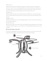
Страница 19: ...dicator LEDs provide status information on the aircraft back to the operator 5 N Description Flashing process of Status Indicator 1 Systems check during power on successful Alternative flashing in red system check green and blueonce 2 Failed system check Slow flashing in red 3 GPS signal acquired or optical flow is functioning Slow flashing in green 4 No sufficient GPS signal or optical flow is no...

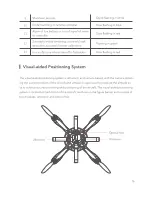
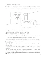
Страница 20: ...re take off is forbidden Slow flashing in red I Visual aided Positioning System The visual aided positioning system is ultrasonic and camera based with the camera obtain ing the current position of the aircraft and ultrasonic wave used to measure the altitude so as to achieve accurate hovering and positioning of the aircraft The visual aided positioning system is located at the bottom of the aircr...

Страница 21: ... may contribute to failure of the optical flow positioning system 1 When the aircraft takes a low altitude flight below 0 Sm at a rapid speed the optical flow positioning system may fail to locate the aircraft 2 Solid color plane 3 A strongly reflective reflective water or transparent surface such as glass floor ice surface and lake surface 4 Flying with excessive speed exceeding 3m s at 1m above ...

Страница 22: ...ally on water in a dark environment or where there is no clear ground texture 5 The ultrasonic waves emitted from the optical flow positioning system can upset animals Ensure no animals are in the proximity when the system is in operation I Propellers PowerEgg uses customized high performance 10 5 inch folding propellers I Intelligent Battery PowerEgg is equipped with a specially designed smart fl...

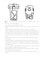
Страница 23: ... last for about two days with no LED indication The battery may heat up slightly which is normal 4 Balance charging protection cell voltage of the battery can be automatically balanced to pro tect the battery 5 Overcharging protection Charging will be automatically stopped when the battery is full 6 Charging temperature protection the battery will be damaged if it is charged at a tempera ture lowe...

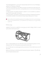
Страница 24: ...ding voltage battery level and current A Please carefully read and abide by the requirements of PowerEgg provided in this manual the disclaimer and the tag on the battery before use The user shall assume the consequences for not using the battery as instructed Battery Usage Installation The battery is installed with wrong plug in protection design so there is no need to worry about which way to pl...

Страница 25: ...w temperatures 10 c to 5 c will lead to abrupt reduction in battery capacity and thus significant reduction in flight duration of the aircraft When battery temperature is between 10 c and 5 C the aircraft cannot take off unless a certain voltage is satisfied Please fully charge the battery and take thermal insulation measures for the battery before use 2 lt s not recommended to use the battery at ...

Страница 26: ...range A Use a standard charger to charge one piece of equipment each time Ensure the battery is turned off before it is installed into or removed from the aircraft Do not insert or remove the battery when it is turned on The smart battery must be charged using the special charger supplied by PowerVision PowerVision will take no responsibility for the consequences of not using the chargers provided...

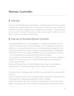
Страница 27: ...chargeable battery in PowerEgg stan dard remote controller has a capacity of 3 000mAh and can continuously work for 20 hours The current battery level may be checked via the battery level indicator The standard remote controller has a built in GPS receiver Easy Control mode is available to the aircraft and the remote controller only when the GPS signal is good otherwise the aircraft cannot be star...

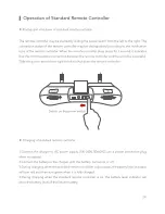
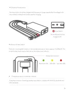
Страница 28: ... and the aircraft is successful Slide the power switch from right to left to shut down the remote controller Switch on the power switch Charging of standard remote controller 1 Connect the charger to AC power supply 100 240V 50 60HZ use a power conversion plug when necessary 2 Connect the battery to the charger with the battery turned on or off 3 During charging when the standard remote controller...

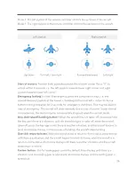
Страница 29: ... with the charger not officially provided by PowerVision Standard Remote Controller 3 5 hours for full charging Control of standard remote controller Left joystick Up and down control the upward and downward movement of the aircraft left and right control the horizontal rotation of the aircraft Right joystick Up and down control the forward and backward movement of the aircraft left and right cont...

Страница 30: ...lly due to loss of power Under normal circumstances the motor may be automatically stopped when the aircraft lands One click takeoff landing button When the aircraft has not taken off press and hold the key until there is a vibration and the aircraft begins to take off when the aircraft takes off press the key again until there is another vibration and the aircraft begins to land short press the k...

Страница 31: ...a three color battery level indicator The indicator shows the battery level of the battery when the remote controller is on whether charging or not In case of charging when the remote controller is off the indicator is red indicating charging when the remote controller is fully charged the indicator is green indicating full charging in case of emergency alarm during flight the battery level indica...

Страница 32: ...click selfie control of 3 axis gimbal pitch taking photos and video shooting Users can easily complete various operations of the aircraft with the assistance of the remote controller The built in rechargeable battery in PowerEgg gesture based remote controller has a capac ity of 1 S00mAh and can continuously work for 10 hours The current battery level may be checked via the battery level indicator...

Страница 33: ...t is successful Slide the power switch from right to left to shut down the remote controller Switch on the power switch Charging of gesture based remote controller 1 Connect the charger to an AC power source 100 240V 50 60HZ use a power converter if necessary 2 Connect the battery and the charger when the battery is on or off 3 During charging when the standard remote controller is shut down the b...

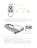
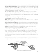
Страница 34: ... Control of gesture based remote controller Gesture based Remote Controller The battery will be fully charged in 2h Start of motor short press takeoff key and then keep pressing landing key complete within 1 second Then the screw propeller is unlocked and started Emergency locking In case of emergency press the combination key i e 3 axis gimbal pitch ascend descend taking photos and camera shootin...

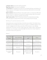
Страница 35: ... the key until there is a vibration for the function of following Taking PhotoNideo shooting button short press the button for photographing keep press ing the key until there is a vibration for videoshooting if it is not in video shooting state and for stopping video shooting if it is in camera shooting state Joystick Joystick up and down control 3 axis gimbal pitch joystick left and right contro...

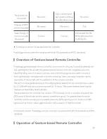
Страница 36: ...n Backlight Color of Three Color Buzzer Prompt Light Aircraft takeoff The backlight of takeoff la landing prompt nding button is normally on No action No action Aircraft return The backlight of return to Dripping sound 1 cycle to home prompt home key is normally on No action for buzz per second Low power alarm No action The red light is Dripping sound 4 cycles normally on for buzz per second Not p...

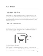
Страница 37: ...ecifications I Operation of Base station Start up and shutdown Press the power switch key for 3 seconds until the indicator near the power key turns on when it is necessary shut down the base station after use press the power switch key for 3 seconds again until all indicators are off OOO n Connection of wireless base station For the connection of wireless base station power on the aircraft and th...

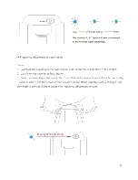
Страница 38: ...e station and wait for the initialization of the aircraft 2 Use Vision to connect to base station 3 Press the power key of the aircraft for 1Os until the tail status indicator in blue flashes slowly 3 seconds later press the power key for 1Os until the tail status indicator in blue changes from slow flash to constant light It enters into frequency adjustment function Blue light flash s slowly fj 4...

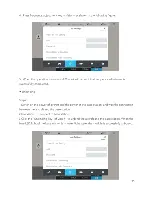
Страница 39: ...mpleted Unbinding Steps 1 Switch on the power of aircraft and the power of the base station and wait the connection between the aircraft and the base station 2 Use Vision to connect to base station 3 Click the Unbinding key of Vision to unbind the aircraft and the base station When the blue LED light of the base station is in water light state the module is successfully unbound N A d Device is not...

Страница 40: ...The module will be fully charged in Sh The built in rechargeable battery of the wireless base station has a capacity of 6 000mAh The current battery level may be checked via the battery level indicator Battery level indicator 000 More than 60 20 60 Less than 20 n Compliance version of remote controller Compliance version PowerEgg wireless base station complies with both CE standards and FCC standa...

Страница 41: ... Following mode the rotation direction of the 3 axis gimbal follows the heading of the aircraft The pitch and heading are controllable but rolling is not FPV mode The motion of the 3 axis gimbal in rolling direction follows the motion of the aircraft in rolling direction Thus users can obtain the experience of the best flight angle of view Precautions 1 Please open the four arms and bottom cap of ...

Страница 42: ...tch video tutorials _ e f l i II r _ a 11111 I Product Description t 1 1 1 a Europe North America To be used for real time transmission from the camera gimbal adjustments setting of way points flight modes electronic fencing and return to home points and flight logs and the storage of pictures and movies taken etc I Introduction to Vision Functions Homepage Start Vision The interface displays the ...

Страница 43: ...A When the equipment is connected click the Start Flying A systems check will com mence Flying is only possible after the aircraft passes the systems check If something fails the systems check it must be resolved prior to flight e 1Q e Sensors RC mode Normal Mode2 I e 0 e SD capacity Gimbal status 10 00G Normal e a remote battery 50 I e aircraft model Manual battery temp 30 C 39 ...

Страница 44: ...aft can guide the flight route and trail via satellite signal Twenty is the maximum number of possible signals received by the GPS of the aircraft Base station signal the strength of signal will impact the efficiency of the aircraft and base station to receive and send information Equipment connection status display of information on connection status of the equip ment Battery level of the aircraf...

Страница 45: ...o home point setting is not set it return to homes to the takeoff point See the Smart return to home section for details Route planning Click waypoint planning to select the planned points on the map and plan a route by point selection on the map and automatic connection The velocity height hovering dura tion and other parameters of each waypoint may be set Upon the completion of planning click St...

Страница 46: ... turns about to face the position of the remote controller Device is not connee jQN A O N A X 0 Waypoint 1 Fly mode H Turn back 0 Safe zone Settings Return to home point setting Return to home point setting includes current position aircraft starting point default value and point selection on the map User position the aircraft automatically return to homes to the current position of the remote con...

Страница 47: ...me and may stop return to home when it enters the electronic fence and keep flying in the original mode ce is not connected jQ N A 1O N A eoo 0000 H N A D N A V S N A N A Positioning Positioning human positioning and aircraft positioning Not connected to the aircraft only human positioning is available Connected to the aircraft both the man and the aircraft are positioned Map layer switching Map m...

Страница 48: ...n view the flying scene of UAV through Vision Taking photos and Video Shooting Shooting module contains video shooting image shooting photo album and camera parame ter settings Video shooting control the camera to shoot a video Image shooting control the camera to shoot an image Photo album to cache the videos and images shot by the aircraft in the process of flight HD original images are stored i...

Страница 49: ...e is not connee _j J N A Flight control settings Aircraft attitude and compass calibration Automatic landing threshold 12 18 V No fly zone O N A X 12 C iQ a o O H N A D N A VS N A N A Remote controller setting Remote controller calibration when the remote controller requires calibration the func tion may be used to calibrate the remote controller Joystick mode users can select appropriate joystick...

Страница 50: ...not conne O N A O N A Link Settings X Select the Channel Automatic selection of channel C Video bit rate Setting ssid Password 4 a o vv vv 0 H N A D N A VS N A N A Battery setting Voltage display on the main screen when the switch is switched on the main screen will display both the current percentage of remaining battery level and voltage In addition some details of the aircraft battery can be fo...

Страница 51: ... will directly skip to the secondary function page I Flight Academy Flight Academy allows you to view the videos messages and other information I Flight Peripherals Flight Peripherals allow you to view flight messages Each message page allows third party sharing and clicking likes I Technical Support Technical Support is to answer the questions about the UAV and provide telephone e mail and relate...

Страница 52: ...tinue locking and start to fly Non no fly zone No fly zone Non no fly zone 8 8 8 ft 7 7 7 7 7 7 7 7 7 7 7 7 7 7 7 See the laws of each country for no fly zones I Safe Flight Conditions and Precautions Flight environment requirements 1 Do not fly in harsh weather such as windy wind speed Scale 5 snowy and rainy weather 2 Beginners are suggested to choose open space for flight avoid high voltage cab...

Страница 53: ...II A II Keep away from crowds trees electric wires tall buildings airports and signal launching towers Radio towers high voltage wires substations and large mag netic metal structures may interfere with its remote controller signals and compass es threatening flight safety 0 0 Q 0 Do not fly in severe weather conditions involving rain smog snow tornados and strong wind speed above 1Om s Do not tou...

Страница 54: ...e station 0000 0 or CD DD I I _ 2 Turn on your phone and connect WIFI Power_ Groundxxx with the password 1234567890 WIFI 0 o WIFI Powei __Groundxxx Enter Password Password 1234567890 3 Start Vision After about 30 seconds click Start Flying when it shows device is connected 0 o PowerVision 0 81 Q A 0 Device is connedted Start Flying 50 ...

Страница 55: ...n be modified or reset To fly the UAV at unfamiliar locations please connect the Internet before connecting the base station and open the APP to zoom in the map to save the data to local cache so as not to affect the normal display of the map during flight 5 Press the power button three times in rapid succession and the landing gear automatical ly closes After the propellers are retracted repeat t...

Страница 56: ...After ensuring the device is connected enter the Start to fly inter face and then click Setup in the lower right corner of the menu bar Then select Flight Attitude and Compass Calibration in the flight setup list Click Calibration to enter the Compass Calibration interface and the compass calibration program starts 2 There are six setting positions in the interface as shown in the figure Calibrati...

Страница 57: ...pward 3 When the three setting positions in the interface are all green the calibration is complete Conditions requiring recalibration 1 The flight site is far from the site of last calibration 2 lt spins in flight or cannot fly in a straight line 53 ...

Страница 58: ...y 0 For the gesture based remote controller press the Ascend key then press and hold the Descend key to start the motor After the motor is started release the key quickly Press the Up key Press and hold the Down key Shut down the motor Under normal circumstances after the aircraft lands on the ground the user will pull the Ascend Descend joystick back to the middle or down to the bottom The aircra...

Страница 59: ...ick action to shut the motor down Standard remote controller Mode 1 Pull the Ascend Descend joystick to the bottom the yaw joystick to the left and press and hold the return to home button till the remote controller vibrates Standard remote controller Mode 2 Pull the ascend descend joystick to the lower left corn er and press and hold the return to home button till the remote controller vibrates G...

Страница 60: ...of the base station Gesture based remote controller Use the data cable to connect the gesture based remote controller the base station Fix the Device in the holder on the surface of the base station Start with the base station remote controller Connect the Device to PowerVision_GroundX WIFI Open the mobile end Vision to enter the initialization state The remote controller in N mode and E mode with...

Страница 61: ...ed slowly pull down the Ascend Descend joystick so that the aircraft slowly and steadily lands on the ground 16 After landing pull the Ascend Descend joystick to its lowest position and hold for more than two seconds until the motor is shut down 17 After shutdown first turn off the aircraft and then the remote controller 57 ...

Страница 62: ...igned to meet the requirements forexposure to radio waves established by the Federal Communications Commission USA These requirements set a SAR limit of 1 6 W kg averaged over one gram of tissue The highest SAR value reported underthis standard during product certification for use when properly worn on the body IC This device complies with Industry Canada s licence exempt RSSs Operation is subject...

Страница 63: ...PowerVision Available on the App Store Get it on Google play Copyright 2017 Powervision Robot Inc All rights reserved ...

Страница 64: ...PowerEgg Unmanned Aerial Vehicle Quick Guide PEGA E1 1 ...

Страница 65: ...aration Download App and then watch tutorials Check the battery and charging Prepare the charger Check the battery Charge Prepare remote controller Prepare aircraft and App 3 Flight and Safety Flight and shooting Flight and shooting with Gesture based control Flight and shooting with Standard remote control Flight Safety ...

Страница 66: ...erEgg MaestroTM simplifies flight operation and gimbal control The 3 axis gimbal camera delivers still images with over 12 million Pixels and 4K UHD 360 degree panoramic video recording PowerEgg s maximum flight speed can reach 50 km h approx 31 mph and its maximum flight time is approximately 23 minutes 1 4K UHD camera on 3 axis gimbal 2 Micro SD card slot 3 Optical positioning sensors and Ultras...

Страница 67: ...can work continuously for 20 hours Users may check battery percentage by the light indicator on the controller 1 Mode switch 2 Left joystick 3 Right joystick 4 Custom button 5 Takeoff land stop landing 6 status battery indicator Return to home stop return to home 8 Top right button take photos videos 9 Right finger wheel gimbal yaw 10 MicroUSB charge port 11 Port connect to base station 12 Power S...

Страница 68: ...also adjust gimbal pitch take pictures and record videos by using the controller PowerEgg MaestroTM controller is powered by a rechargeable battery with a capacity of 1S00mAh It can work continuously for 10 hours Users may check battery percentage by the indicator lights 1 Status Battery indicator s J 2 Joystick gimbal control 3 Custom button r 4 Ascend button 5 Descend button tiij 6 Take off land...

Страница 69: ... ideal environment is 3 1 miles 2 G O J 7 V 0000 r 0 0 0 0 4 0 _ How to use bracket is presented in the graph I Refer to user manual or websites for supported devices Depending on the local law and environment transmitting distance in CE zone will shorten accordingly 04 1 Battery indicator 2 lmage transmitting signal indicator 3 Power switch 4 Cell phone Connection Bracket 5 Tablet Connection Brac...

Страница 70: ...t our product specifications Flight preparation Please download Vision App and watch PowerEgg tutorial videos Please Scan QR code or download Vision App From Apple App store or Google Play Watch video tutorials in Vision or on our official website 05 ...

Страница 71: ...D D D Standard Controller l 111 Turn on the power 06 Check the battery indicator Each light indicates 25 battery level Press the button of battery the illuminated lights indicate the battery remaining capacity Check the battery indicator 30 or above 10 30 less than 10 ...

Страница 72: ...MaestroTM Check the battery indicator 30 or above 10 30 less than 10 Turn on the power Base Station Check the battery indicator 000 60 or above 20 60 less than 20 Turn on the power 07 ...

Страница 73: ...se Station can be charged simultaneously G Aircraft Battery can take 2 5 hours to be fully charged Standard battery can take 3 5 hours to be fully charged 08 MaestroTM battery can take 2 hours to be fully charged I Base Station battery can take 5 hours to be fully charged ...

Страница 74: ...on and the controller through cable t Please connect through this port Please connect through this port If using the standard controller place the base station on the bracket of the standard controller and connect them through cable Please connect through this port Please connect through this port 09 ...

Страница 75: ...n as shown in picture There will be have a clicking sound Indicating that they are in position 2 Open the top battery cover Press the battery into chamber while holding the arms Attention Do Not put pressure on the battery as it may cause damage to the landing gear 10 ...

Страница 76: ...mbal cover off the bottom 4 Press once and then long press the power button until the blue light is on After the notification sound press the power button 3 times in quick succession to deploy the landing gear I 11 ...

Страница 77: ...ith both hands 6 Place the aircraft at a safe distance over 10 meters away from people on suitable ground The head of the aircraft should face the direction that the pilot is facing Safe Radius 1Om Head of the aircraft 12 ...

Страница 78: ...rd controller or Maestro and base station 0000 s r c J or t CD DD I I 8 Turn on your mobile device and connect WIFI Power_Groundxxx Password is 1234567890 0 o Enter Password WIFI Password 1234567890 WIFI Power_Ground O 13 ...

Страница 79: ...er or MaestroTM turns green This indicates the aircraft is prepared for unlocking and flight I I The Wi Fi communication frequency of the base station is SG Mobile phones that do not support SG Wi Fi will not be able to connect to the base station Users may change or reset Wi Fi password anytime using the Vision App When you go the place you never flied before please open the app and zoom in and m...

Страница 80: ...hree times in rapid succession the landing gear will automatically close Close the arms one by one by depressing the trigger located on the under side making sure to position the propellers so that they fit into the cavity J 12 Take out the battery Press the battery lock with thumb and index finger while pulling out the battery 15 ...

Страница 81: ...full control of the aircraft through gestures and movement of the controller Using PowerEgg Maestro gesture based controller to control flight and shooting After connecting to the base station and gesture based controller Vision App shows Simple Flight Mode Safe to fly Short press ascend button Long press takeoff landing button B N 16 1 Press ascend button once then press and hold descend button t...

Страница 82: ...control Press and hold ascend button to desired height then use the gesture based control button to navigate the aircraft by body gestures Gesture based control experience 0 1 Camera Shutter Record Button Bl 17 4 You can control the gimbal and take photos and videos during the flight ...

Страница 83: ...ely as shown in the picture Aircraft will cease function and fall Be wary of your surroundings MaestroTM is not supported for indoor flight Using standard controller to control flight and shooting Mode 2 is the default setting for PowerEgg s remote controller The left stick controls Throttle and Yaw and the right stick controls Pitch and Roll Remote controller has mode 1 and 2 that you can set in ...

Страница 84: ...on on standard remote controller until it vibrates aircraft will rise and hover in the air 4 You can control the gimbal and take photos or videos during the flight 5 Landing Slowly pull the throttle stick to let the aircraft land smoothly Then pull the throttle stick to the very bottom for 2 seconds until motors stop spinning Automated Landing After long pressing the take off I landing button on s...

Страница 85: ...e wires and large magnetic metal structures may influence the aircraft and cause safety issues 0 Q Do NOT fly in severe weather conditions such as those involving snow rain smog tornados and strong wind wind speed above 10m s Please do not touch spinning propellers otherwise it will cause serious personal and property damage 20 No fly zone Please refer to following website http knowbeforeyoufly or...

Страница 86: ...igned to meet the requirements forexposure to radio waves established by the Federal Communications Commission USA These requirements set a SAR limit of 1 6 W kg averaged over one gram of tissue The highest SAR value reported underthis standard during product certification for use when properly worn on the body IC This device complies with Industry Canada s licence exempt RSSs Operation is subject...

Страница 87: ...n the App Store Get it on Google play AMERICA EUROPEAN UNION 1 855 562 6699 358 942 450 547 FRANCE GERMANY 33 975 186 604 49 157 3599 7721 POLAND NETHERLANDS 48 22 307 2388 31858885010 Copyright 2017 Powervision Robot Inc All rights reserved FINLAND 358 942 450 547 SPAIN ill 34 518 880 950 _ CZECH REP 42 035 888 0180 ...

Отзывы: