background image

R&D – TECHNICAL SPECIFICATION DT0424-E01


Powertronix spa reserves the right to modify this document without notice 


Page

3 of 73


5.1.3


DE0098 Relay & Communication Board.....................................................46


5.1.4


DE0138 Temperature sensor PCB .............................................................47


5.1.5


DE0143 Battery Fuse PCB (Battery 7.2-9Ah) /  DE0157 Battery Fuse PCB   

(Battery 4.5-5.2Ah) ...................................................................................................47


5.1.6


DE0150 Control Logic.................................................................................48


5.1.7


DE0151 Inverter Driver & Feedback Alcor..................................................59


5.1.8


DE0152 Inverter Driver & Feedback Mizar .................................................65


5.1.9


DE0153 Power Supply Board .....................................................................69


5.1.10


DE0154 H-F Filter Mizar .............................................................................70


5.1.11


DE0155 LCD Mimic Display .......................................................................71


5.1.12


DE0161 H-F Filter Alcor..............................................................................72


5.1.13


DE1235 Battery String ................................................................................73


Содержание Mizar-Alcor DT 0424

Страница 1: ... the right to modify this document without notice POWERTRONIX Mizar Alcor Service Manual DT 0424 Document DT0424 PTX English Revision Date Checked Approved 00 14 03 2008 18 03 2008 Ghezzi R 21 03 2008 Gorlani A 01 19 05 2008 19 05 2008 Pirola G 20 05 2008 Gorlani A ...

Страница 2: ...ponent Layout 13 2 8 3 CS0150 MIZAR ALCOR Control Logic Board 14 2 8 4 CS0153 MIZAR ALCOR Power Supply Board 15 2 8 5 CS0098 MIZAR ALCOR Relay Communication Board 16 2 8 6 MIZAR ALCOR SNMP Communication Board 16 2 8 7 CS0161 MIZAR ALCOR Terminal Blocks Board 17 3 TROUBLESHOOTING 18 3 1 FUSE CHECK LIST 18 3 2 POWER FUSE 19 3 2 1 Mizar 19 3 2 2 Alcor 20 3 3 CHECK ALL PFC INVERTER OUT IGBTS 21 3 3 1 ...

Страница 3: ...nsor PCB 47 5 1 5 DE0143 Battery Fuse PCB Battery 7 2 9Ah DE0157 Battery Fuse PCB Battery 4 5 5 2Ah 47 5 1 6 DE0150 Control Logic 48 5 1 7 DE0151 Inverter Driver Feedback Alcor 59 5 1 8 DE0152 Inverter Driver Feedback Mizar 65 5 1 9 DE0153 Power Supply Board 69 5 1 10 DE0154 H F Filter Mizar 70 5 1 11 DE0155 LCD Mimic Display 71 5 1 12 DE0161 H F Filter Alcor 72 5 1 13 DE1235 Battery String 73 ...

Страница 4: ...ferencing is inevitable therefore it is recommended that this chapter is read in its entirety before commencing work on the equipment There is no practical way detecting an impending UPS malfunction as most problems do not emerge as a gradual performance degradation Generally the UPS will either work correctly or shut down with or without a warning indication In the event of a UPS malfunction trou...

Страница 5: ...lowing test equipment will be required 1 2 1 Portable PC with software POWERTRONIX UPS Maintenance UCT See the chapter 4 is absolutely necessary for a skilled service engineer because every set point or UPS logic status or regulation constant can be set or checked only via PC and POWERTRONIX software 1 2 2 Oscilloscope A dual trace oscilloscope which has the ability to sum the two channel allowing...

Страница 6: ...ing pages To check pictures it s necessary to follow the UPS general schematic diagram DE1111 for Mizar and DE1112 for Alcor attached at the end of this document 2 1 UPS CLOSED Fig 1 WARNING Before removing safety covers after power disconnection it s necessary to wait for 10 minutes to have discharged inner capacitors In any case be careful and never touch circuits or components before a voltage ...

Страница 7: ...ATION DT0424 E01 Powertronix spa reserves the right to modify this document without notice Page 7 of 73 2 2 INNER VIEW WITH SAFETY COVER REMOVED Fig 2 UPS Power Section UPS Battery Location BATTERY Connections BATTERY String ...

Страница 8: ...ix spa reserves the right to modify this document without notice Page 8 of 73 2 3 REAR UPS DESCRIPTION Fig 3 Terminal Blocks Power Connection Rotary Switch Breaker SNMP Net Com Slot location RS232 Status Remote Control Slot location Output Air window ...

Страница 9: ...onix spa reserves the right to modify this document without notice Page 9 of 73 2 4 MIZAR ELECTRONIC PARTS LAYOUT LEFT SIDE Fig 4 RIGHT SIDE Fig 5 NEUTRAL BAR Connection DC Busbar HEATSINK FAN Power Impedence DC Busbar Power Impedence CS0150 CS0153 ...

Страница 10: ... spa reserves the right to modify this document without notice Page 10 of 73 2 5 ALCOR ELECTRONIC PARTS LAYOUT LEFT SIDE Fig 6 RIGHT SIDE Fig 7 NEUTRAL BAR CONNECTION DC Busbar HEATSINK Power Impedence DC Busbar Power Impendence Fuse Fuse CS0153 CS0150 ...

Страница 11: ...Holder x 7 9 Ah DE0157 CS0157 0sde 0154 H F Filter DE0154 CS0161 0sde 0162 Temperature Sensor SMT DE0138 CS0138 0sde 0098 Relay Board DE0098 CS0098 2 7 ALCOR BOARDS This paragraph describes the PCB s fitted in the UPS Subassembly code Description Diagram Circuit code 0sde 0150 Control Logic 7 30KVA DE0150 CS0150 0sde 0151 Inverter Drivers Feedback Mizar DE0151 CS0151 0sde 0153 Aux Converter DE0153...

Страница 12: ...OARDS LAYOUT 2 8 1 CS0152 MIZAR Power Interface Board Component Layout Refer to Electrical Diagram DE0152 Fig 8 Input Precharge Relay Negative DC Capacitor Fuse Negative DC Battery Fuse RESERVE Relay Static Switch Positive DC Battery Fuse Positive DC Capacitor Fuse IGBT Input Section IGBT Output Section INVERTER Relay Static Switch ...

Страница 13: ...modify this document without notice Page 13 of 73 2 8 2 CS0151 ALCOR Power Interface Board Component Layout Refer to Electrical Diagram DE0151 Fig 9 Input Precharge Thyristor IGBT INPUT SECTION RESERVE Static Switch Thyristor IGBT OUTPUT SECTION INVERTER Static Switch Thyristor ...

Страница 14: ...ice Page 14 of 73 2 8 3 CS0150 MIZAR ALCOR Control Logic Board Refer to Electrical Diagram DE0150 Fig 10 Fiber Optic Connector Parallel Communicatio LCD Mimic Display Board Connectors LED BAR UPS STATUS LED BAR Processor STATUS Battery Keep Timer Interface Board Connectors Relay Board Connectors SNMP Connector ...

Страница 15: ...ves the right to modify this document without notice Page 15 of 73 2 8 4 CS0153 MIZAR ALCOR Power Supply Board Refer to Electrical Diagram DE0153 Fig 11 Input Mains Connector Input Reserve Connector DC Bus Connector Interface Board Connector Power Supply status ...

Страница 16: ...ommunication Board Refer to Electrical Diagram DE0098 Fig 12 2 8 6 MIZAR ALCOR SNMP Communication Board Fig 13 DB9 RS232 Communication Connector E P O Terminal Connection Free voltage contacts Ups status Control Logic Connector Control Logic Connection Config Switch NET RJ45 status led CONNECTOR Serial Comport Aux Input Output Drycontact Status Led Error Link ...

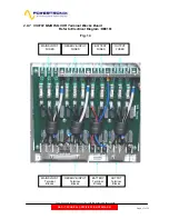
Страница 17: ...ument without notice Page 17 of 73 2 8 7 CS0161 MIZAR ALCOR Terminal Blocks Board Refer to Electrical Diagram DE0161 Fig 14 BATTERY Terminal Blocks OUTPUT Terminal Blocks MAINS INPUT Terminal Blocks RESERVE INPUT Terminal Blocks BATTERY FUSES OUTPUT FUSES MAINS INPUT FUSES RESERVE INPUT FUSES ...

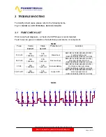
Страница 18: ...orner DE0154 MIZAR DE0161 ALCOR F7 F8 32A 10X38mm 50A 14x51mm External Battery EMC RF FILTERS BOARD CS0161 Front high centre right corner DE0154 MIZAR DE0161 ALCOR F9 F10 F11 32A 10X38mm 50A 14x51mm Output UPS EMC RF FILTERS BOARD CS0161 Front high right corner DE0154 MIZAR DE0161 ALCOR SCH 1 C9 0 47µF 275Vac X2 PW34 PW33 PW8 L3 R C6 1µF 275Vac X2 C7 0 47µF 275Vac X2 F4 PW6 L1 R PW9 N R PW35 PW7 L...

Страница 19: ...GB128 28 6 13 27 2 1 24 12 5 23 F2 32A 10x38 1 2 3 4 C37 2 2µF PHB 850V 2 1 FS21 L2 Q6 SK60GB128 28 6 13 27 2 1 24 12 5 23 R180 150K 0 25W R186 100K 0 25W FS14 DC R181 150K 0 25W R188 150K 0 25W C38 2 2µF PHB 850V 2 1 Q2 SK60GB128 28 6 13 27 2 1 24 12 5 23 C43 2 2µF PHB 850V 2 1 Q4 SK60GB128 28 6 13 27 2 1 24 12 5 23 R96 150K 0 25W C40 2 2µF PHB 850V 2 1 R97 150K 0 25W FS4 L3 C41 2 2µF PHB 850V 2 ...

Страница 20: ...COR LEFT RIGHT SIDE electronic parts LAYOUT TAB 3 Fuse Value Protection of Location F1 F3 100A 690V Positive Battery Input Positive DC BUS Right side Heatsink DE0152 ALCOR F2 F4 100A 690V Negative Battery Input Negative DC BUS Left side Heatsink DE0152 ALCOR If you find one or more fuses blown you have to check firstly ALL the POWER semiconductors on the UPS ...

Страница 21: ... to indicate the part of circuit Obviously also PFC L2 L3 and INVERTER L1 L2 L3 driver has to be tested SCH 3 P 15 P 15 HF supply 1 HF supply 2 DRV_L1 TOP_ING DRV_L1 BOTT_ING G1 T E1 T G1 B E1 B R4 1 8K R10 270 R28 270 R19 1 8K D4 UF4007 2 1 Z4 15V 2 1 C7 100µF 35V TP1 D10 1N4148 2 1 T1 VAC4721X004 1 6 3 2 4 5 C1 100µF 35V D13 1N4148 2 1 C16 100µF 35V Totem ISO4 HCPL3120 2 3 6 5 8 7 R13 1K C10 100...

Страница 22: ...r has to be tested SCH 4 P 15 P 15 HF supply 1 HF supply 2 DRV_L1 BOTT_ING G1 T E1 T DRV_L1 TOP_ING E1 B G1 B R10 270 R4 1 8K R19 1 8K R28 270 C7 100µF 35V Z4 15V 2 1 D4 UF4007 2 1 D10 1N4148 2 1 TP1 C1 100µF 35V T1 VAC4721X004 1 6 3 2 4 5 R13 1K Totem ISO4 HCPL3120 2 3 6 5 8 7 C16 100µF 35V D13 1N4148 2 1 R22 10 TP10 Totem ISO1 HCPL3120 2 3 6 5 8 7 C10 100µF 35V Z10 P6KE18CAC250 2 1 D1 1N4148 2 1...

Страница 23: ... flyback dc dc insulated converter that gives regulated dc voltages on the output to all the boards of the UPS Each line coming in are protected with fuse on the board Name Description Value Note F1 F2 Positive and Negative DC input 1A 5x20 Fig 15 F3 F4 F5 Input Mains AC L1 L2 L3 input 1A 5x20 Fig 15 F4 F5 F6 Reserve Input AC L1 L2 L3 input 1A 5x20 Fig 15 Output dc voltages status is monitored by ...

Страница 24: ...age 3a DC Output 7 5Volt dc check between TP7 TP9 DC Voltage 7 5Vdc 3b DC Output 15Volt dc check between TP7 TP4 DC Voltage 15Vdc 3c DC Output Isolated 15Volt dc check between TP14 TP12 DC Voltage 15Vdc Safe Life Battery remote UPS s location function During battery discharging the battery voltage is monitored by the control board when the battery voltage reaches the minimum value the inverter is ...

Страница 25: ...t Volt is present DL2 Yellow ON when Power supply 12Volt Volt is present DL3 Green ON when Power supply 12 Volt is inside the right parameters SW1 Push Button SW2 Push Button Upload STL Software Enable Function LED BAR UPS STATUS LED BAR Processor STATUS SW1 Button Not Used SW2 Button Up load software micro LED DL1 Green Power Supply 5 Volt Enabled LED DL2 Yellow Power Supply 12 Volt Enabled LED D...

Страница 26: ...f the UPS The second BAR of LED M1 M4 show the status of the Microprocessor inside the control Name Colour Description ON OFF BLINKING L1 Green Mains Line Status MAINS is OK Mains is not OK PFC overload L2 Green Battery Status Battery VOLT OK Battery VOLT NOK Battery Prealarm L3 Green Inverter Status RUNNING NOT RUNNING INV overload L4 Green Reserve Line Status Res Line is OK Res Line is not OK Ph...

Страница 27: ...52 17 5Vdc 15 20Vdc P 7 5 Input Power Supply from CS0152 TP61 TP58 7 5Vdc 7 5 10Vdc P 12 Internal stabilized Power Supply TP55 TP53 12Vdc 11 75 12 25Vdc P 5 Internal stabilized Power Supply TP61 TP59 5Vdc 4 75 5 25Vdc P 3 3 Internal stabilized Power Supply TP61 TP63 3 3Vdc 3 1 3 5Vdc P 1 5 Internal stabilized Power Supply TP61 TP64 1 5Vdc 1 4 1 6Vdc N 7 Internal Power Supply TP61 TP67 7Vdc 6 10Vdc...

Страница 28: ...acitors Fuse 12 DE0152 Pag 2 Negative Battery Fuse Protection 13 DE0152 Pag 2 Snubber Capacitors 14 DE0152 Pag 2 J4 50 pin Flat Cable Connector to Control Logic CS 0150 15 DE0152 Pag 4 J5 40 pin Flat Cable Connector to Control Logic CS 0150 16 DE0152 Pag 4 J7 20 pin Flat Cable Connector to Auxiliary Power Supply CS 0153 17 DE0152 Pag 4 CN9 2 Pin Molex Connector to Thermal Sensor C External Battery...

Страница 29: ...owertronix spa reserves the right to modify this document without notice Page 29 of 73 MIZAR Interface Board Component Layout Refer to Electrical Diagram DE0152 Fig 17 1 2 3 4 5 6 7 8 9 10 11 12 13 14 15 16 17 18 19 20 21 22 23 24 25 26 27 28 ...

Страница 30: ...le Connector to Control Logic CS 0150 7 DE0151 Pag 6 J2 14 pin Flat Cable Connector to Control Logic CS 0150 8 DE0151 Pag 6 J3 20 pin Flat Cable Connector to Auxiliary Power Supply CS 0153 9 DE0151 Pag 6 CN11 2 Pin Molex Connector to Thermal Sensor C External Battery Box 10 DE0151 Pag 6 CN9 2 Pin Molex Connector to Thermal Sensor C Internal Battery Box 11 DE0151 Pag 6 CN8 2 Pin Molex Connector Not...

Страница 31: ...DT0424 E01 Powertronix spa reserves the right to modify this document without notice Page 31 of 73 ALCOR Interface Board Component Layout Refer to Electrical Diagram DE0151 Fig 18 10 11 12 13 14 15 16 6 7 9 17 8 1 2 3 19 18 20 4 5 ...

Страница 32: ...e UPS parameters which are not accessible through LCD panel Necessary things PC with program installed serial communication cable DB9 DB9 and RS232 Relay board CS0098 standard on board Below there is a short description of the program and its possibilities Few seconds after start the program will be ready to use The initial screen is similar to the following picture As there is no standard way of ...

Страница 33: ...s port number speed etc of last successful transmission and uses them later as default settings Below there is description of main program functions Attention all further explanations refers to the Alcor Mizar and R D user access level Depending on the program version R D service user some functions may be hidden or disabled 1 UPS identification button Opens window containing UPS identification in...

Страница 34: ...t without notice Page 34 of 73 2 UPS configuration button Opens window containing three tabs as described below Main configuration tab This tab contains essential UPS parameters parallel mode and batteries settings output parameters frequency number of phases and others Nominal values tab 2 press ...

Страница 35: ...o the form With any tab the user can read the informations from the UPS or from the file modify them and write back to the UPS The program operates read write operations on the parameters which are present on visible tab only 3 UPS status and meters button This button opens the window containing four different tabs as described below All of them except of the last one called UDBS Obj history use t...

Страница 36: ...the UPS and 5 sections with values of measures When the Idle read mode is active all the tab content is refreshed every second UDBS object 2 to 9 tab This tab gives an access to several informations available in UDBS protocol The user can choose from 1 to 6 different parameters from the lists and watch them simultaneously When the Idle read mode is active all the tab content is refreshed every sec...

Страница 37: ...ral important internal UPS signals It can be useful in the case of UPS malfunction servicing or maintenance As for the previous tabs also this tab content is refreshed every second if the Idle read mode is activated UDBS object history tab Using this tab user can download event log content from the UPS Updated log can be also saved to the file button Save to file or File Save UPS ...

Страница 38: ... tabs this one does not use Idle read mode 4 Commands and update button This button opens the window containing two tabs as described below UPS commands tab This tab contains several UPS commands which can be useful while UPS service or maintenance To send the command to the UPS the user should choose the command and click Execute command Software updates tab 4 press ...

Страница 39: ...e enabled and ready to use 5 Power voltage button This button opens the window with three tabs containing important internal numeric values of the UPS Normally all the values are set correctly in the factory and there is no need to modify them 6 UPS setup button This button opens UPS setup window which contains some of the power voltage UPS values used while performing unit setup process in the fa...

Страница 40: ...eral diagram Mizar DE1112 UPS general diagram Alcor DE0098 Relay Communication Board DE0138 Temperature sensor PCB DE0143 Battery Fuse PCB gap18mm DE0150 Control Logic DE0151 Inverter Driver Feedback Alcor DE0152 Inverter Driver Feedback Mizar DE0153 Power Supply Board DE0154 H F Filter Mizar DE0155 LCD Mimic Display DE0157 Battery Fuse PCB gap22mm DE0161 H F Filter Alcor DE1235 Battery String ...

Страница 41: ...ule Temp 0SDE162 1 2 UPS_GND NEUTRAL BAR UPS_GND PW5 PW9 PW12 NEUTRAL BAR PW16 VT1 0CEVTM2204P16W L6 DSM191 C1 20µF 400 450V I1 Rotary Switch 2 4 3 6 1 5 I1 Rotary Switch 39 40 R2 PRCH Resitor 50W L5 DSM191 C2 20µF 400 450V L1 DSM191 R1 PRCH Resitor 50W C5 10µF 400 450V I1 Rotary Switch 27 28 C9 10µF 400 450V P1 1 2 C8 10µF 400 450V C7 10µF 400 450V P3 1 2 P4 1 2 P2 1 2 P5 1 2 P6 1 2 P8 1 2 P7 1 2...

Страница 42: ...IN CE4 4400µF 450V CE2 4400µF 450V L3 DSM191 L2 DSM191 L1 DSM191 FS8 L2 IN FS9 L3 IN FS43 N IN FS25 L1 FS24 L2 FS23 L3 L4 DSM191 L5 DSM191 L6 DSM191 FS20 L1 FS28 L1 CE1 4400µF 450V FS29 L1 OUT FS31 L3 OUT CE3 4400µF 450V FS22 L3 FS21 L2 FS26 L3 FS27 L2 C3 20µF 400 450V C2 20µF 400 450V FS30 L2 OUT C1 20µF 400 450V Q1 28 6 13 27 2 1 24 12 5 23 Q2 28 6 13 27 2 1 24 12 5 23 FS2 L2 FS3 L3 FS1 L1 Q3 28...

Страница 43: ...R UPS_GND UPS_GND NEUTRAL BAR PW16 PW5 PW9 PW12 VT1 0CEVTM2204P16W I1 Rotary Switch 1 3 4 5 2 6 R2 PRCH Resitor 50W C7 10µF 400 450V C8 10µF 400 450V I1 Rotary Switch 39 40 C9 10µF 400 450V L4 DSM192 L5 DSM192 L6 DSM192 C2 40µF 400 450V C1 40µF 400 450V C3 40µF 400 450V 35 36 R1 PRCH Resitor 50W I1 Rotary Switch 27 28 P1 1 2 P3 1 2 P4 1 2 P2 1 2 P5 1 2 P6 1 2 P8 1 2 P7 1 2 P9 1 2 P10 1 2 P11 1 2 P...

Страница 44: ...3 PW8 L2 PW27 L3 PW5 L2 PW6 L3 PW4 L1 R83 10k R80 10k R63 22k 0 25W R61 22k 0 25W R87 27k 0 25W R96 27k 0 25W R97 27k 0 25W R92 27k 0 25W R88 27k 0 25W R91 27k 0 25W CN2 INPUT MAINS C44 0 1µF MABA01 C43 0 1µF MABA01 R81 10 5W CN1 DC BUS 1 2 3 4 C45 0 1µF MABA01 R79 10 5W R78 10 5W R62 22k 0 25W PW25 L1 S1 SCR SKUT85 3 5 1 2 4 6 7 10 13 12 14 11 R95 1k C47 1000pF C51 10µF C48 10µF U1 SG3525 2 1 3 5...

Страница 45: ... 27k 0 25W R135 27k 0 25W R162 27k 0 25W R136 27k 0 25W R163 27k 0 25W R166 27k 0 25W R137 27k 0 25W R161 27k 0 25W R165 27k 0 25W K8 N O FS11 FS12 FS9 TO NEUTRAL BAR S2 SCR SKUT85 3 5 1 2 4 6 7 10 13 12 14 11 R151 10 5W C67 0 1µF MABA01 C69 0 1µF MABA01 C73 0 1µF MABA01 R155 10 5W R156 10 5W R147 27k 0 25W R144 27k 0 25W R141 27k 0 25W PW20 L3 S3 SCR SKUT85 3 5 1 2 4 6 7 10 13 12 14 11 PW19 L2 PW...

Страница 46: ... TP1 R13 100 D5 1N4148 R14 100 T1 TRANSFORMER FLAT 2 2 1 3 4 2 8 7 5 6 Z1 47V C5 1µF R3 1 2K R2 100 Q1 2N2222 R1 100 IC3 4N35 1 2 5 4 6 R17 470K C8 0 1nF 50V R15 1K C7 1nF 50V R11 100 K1 12V 12A 4 5 3 1 2 R4 22 C4 1µF D1 1N4148 R8 10K CN1 1 2 D2 1N4148 Z3 12V Z2 12V R10 470K K2 12V 12A 4 5 3 1 2 K3 12V 12A 4 5 3 1 2 D3 1N4148 K4 12V 12A 4 5 3 1 2 D4 1N4148 C1 1µF C3 1µF D10 1N4148 C9 1µF Z4 12V C2...

Страница 47: ...otice Page 47 of 73 5 1 4 DE0138 Temperature sensor PCB R1 R4 C1 1uF 25V J1 1 2 U1 LM334M 1 2 3 4 5 6 7 8 RESISTOR TABLE R1 R4 18 ohm 4 7 ohm 10µA K ALCOR MIZAR 0SDE0162 5 1 5 DE0143 Battery Fuse PCB Battery 7 2 9Ah DE0157 Battery Fuse PCB Battery 4 5 5 2Ah FS4 FASTON F FS3 FASTON F FS2 FASTON F FS1 FASTON F ...

Страница 48: ...ed 2 1 U15C ULN2003A 3 14 U15B ULN2003A 2 15 RP4 470 1 2 3 4 5 6 7 8 U15E ULN2003A 5 12 U15D ULN2003A 4 13 U15F ULN2003A 6 11 RP6 470 1 2 3 4 5 6 7 8 RP5 470 1 2 3 4 5 6 7 8 RP1 470 1 2 3 4 5 6 7 8 U15G ULN2003A 7 10 U16A ULN2003A 1 16 9 8 RP2 470 1 2 3 4 5 6 7 8 L8 Green 2 1 L 6 Red 2 1 DEBUG STATUS LED UPS STATUS LED OK LD3 INVERTER STATUS MASTER SYNCRO OK LOAD NOT FEED LOAD ON RES BATTERY OK OK...

Страница 49: ... U18A 1 2 14 7 U19C ULN2003A 3 14 R7 1M C7 1µF U19D ULN2003A 4 13 C8 0 1µF U19E ULN2003A 5 12 R8 1M C9 1µF U18B 3 4 14 7 R9 100K C5 1nF R5 100K C10 0 1µF U17E 11 10 14 7 RP10 10K 1 2 3 4 5 6 7 8 SW2 PBswitch 1 3 SW1 RESET CL 1 3 C1 1µF U17A 1 2 14 7 R1 1M RP7 10K 1 2 3 4 5 6 7 8 C6 0 1µF RP8 470 1 2 3 4 5 6 7 8 C2 1µF C3 1µF R166 1K U17D 9 8 14 7 C4 1µF R4 100K U19F ULN2003A 6 11 U19G ULN2003A 7 1...

Страница 50: ... Ein Dout Din R65 0 ohm R64 NOT MOUNTED R25 82K R48 1K C35 10nF R42 82K R55 82K R171 1K R30 10K R31 10K C24 0 1µF C26 0 1µF U14A LM324 3 2 1 4 11 R28 10K R27 22K R29 22K R67 1K C42 10nF C135 100µF 10V R12 2 2K R11 470 R69 10M R13 470 D2 1N4148 2 1 R74 1K C47 10nF R14 2 2K U8 HCF4067BM 10 11 14 13 15 1 9 8 7 6 5 4 3 2 23 22 21 20 19 18 17 16 24 12 A B C D INBT OUT I0 I1 I2 I3 I4 I5 I6 I7 I8 I9 I10 ...

Страница 51: ..._L3 BOTT_ING DRV_L1 TOP_ING DRV_L2 BOTT_ING C54 0 1µF T otem U22B ICL7667 4 5 1 8 C55 0 1µF C56 0 1µF T otem U23B ICL7667 4 5 1 8 C51 0 1µF T otem U23A ICL7667 2 7 6 3 T otem U24A ICL7667 2 7 6 3 T otem U24B ICL7667 4 5 1 8 R82 100 R88 100 R86 100 R83 100 R84 100 R90 100 R81 100 R85 100 R89 100 R87 100 R91 100 T otem U25B ICL7667 4 5 1 8 T otem U22A ICL7667 2 7 6 3 R80 100 T otem U25A ICL7667 2 7 ...

Страница 52: ...CR_L1 T otem U28A ICL7667 2 7 6 3 T otem U28B ICL7667 4 5 1 8 R94 100 TP88 TP87 R92 100 T otem U29A ICL7667 2 7 6 3 T otem U29B ICL7667 4 5 1 8 R96 100 R98 100 TP90 TP89 R158 1K C61 0 1µF C60 0 1µF T otem U33B ICL7667 4 5 1 8 T otem U31A ICL7667 2 7 6 3 T otem U31B ICL7667 4 5 1 8 R95 100 R93 100 R97 100 RP15 470 1 2 3 4 5 6 7 8 R156 1K R157 1K RP17 470 1 2 3 4 5 6 7 8 U38G ULN2003A 7 10 9 8 U38F ...

Страница 53: ...µF TP42 U5 EPCS1 2 6 1 5 4 7 8 3 DATA DCLK NCS ASDI GND VCC VCC VCC RP20 10K 1 2 3 4 5 6 7 8 R105 1M C66 33pF R108 1K C67 33pF R107 220 CN_PRG1 10p 2 54 1 2 3 4 5 6 7 8 9 10 BT1 3V Lithium 512Kx8bit 256kx16bit U4 AM29LV400 TSOP48 1 2 3 4 5 6 7 8 9 10 11 12 13 14 15 16 17 18 19 20 21 22 23 24 48 47 46 45 44 43 42 41 40 39 38 37 36 35 34 33 32 31 30 29 28 27 26 25 A15 A14 A13 A12 A11 A10 A9 A8 NC NC...

Страница 54: ... 6 3 T otem U49B ICL7667 4 5 1 8 T otem U44B ICL7667 4 5 1 8 T otem U49A ICL7667 2 7 6 3 C71 0 1µF U38A ULN2003A 1 16 9 8 U38B ULN2003A 2 15 9 8 U35D 40106 9 8 14 7 C70 0 1µF U35B 40106 3 4 14 7 U35A 40106 1 2 14 7 U35C 40106 5 6 14 7 TP43 TP45 TP44 C77 0 1µF RP30 470 1 2 3 4 5 6 7 8 RP29 470 1 2 3 4 5 6 7 8 RP28 470 1 2 3 4 5 6 7 8 C74 0 1µF C78 0 1µF RP24 10K 1 2 3 4 5 6 7 8 RP25 10K 1 2 3 4 5 6...

Страница 55: ... 3 4 5 8 TP46 T otem U50A ICL7667 2 7 6 3 C137 0 1µF TP47 TP51 R140 1K TP50 U35E 40106 11 10 14 7 U35F 40106 13 12 14 7 R138 10K C128 0 1µF U39D 40106 9 8 14 7 R109 10K C80 1nF U39A 40106 1 2 14 7 C79 0 1µF U38D ULN2003A 4 13 9 8 U39E 40106 11 10 14 7 U39F 40106 13 12 14 7 R116 560K R115 10K R114 2 2K R113 1K R112 2 7K R111 270 Q1 1 2 3 ISO2 4N35 1 2 4 6 5 R117 560K T otem U50B ICL7667 4 5 1 8 U39...

Страница 56: ... 158 159 160 161 162 163 164 165 166 167 168 169 173 174 175 177 178 179 180 41 42 43 44 45 46 47 48 49 53 54 56 57 58 59 60 VCCIO4 VCCIO4 VCCIO4 VCCIO3 VCCIO3 VCCIO3 VCCIO2 VCCIO2 VCCIO2 VCCIO1 VCCIO1 VCCIO1 VCCA_PLL2 VCCA_PLL1 GNDG_PLL2 GNDG_PLL1 GNDA_PLL2 GNDA_PLL1 GND GND GND GND GND GND GND GND GND GND GND GND GND GND GND GND GND GND DEV_CLRN DEV_OE INIT_DONE PLL2_OUT1P PLL2_OUT1N PLL1_OUT0P ...

Страница 57: ... 2 IN OUT REF TP61 C120 10µF 35V DL3 Green 2 1 C123 0 1µF U43 NCP1117DT15 3 2 1 IN OUT REF DL1 GREEN 2 1 R131 680 R134 1K R125 1K C121 10µF 35V C122 0 1µF C117 0 1µF C111 10µF 35V C115 10µF 35V C116 10µF 35V C118 0 1µF DL2 Y ELLOW 2 1 C113 0 1µF Q2 BDX54 1 2 3 U41 7805 1 3 2 IN OUT REF U42 LM2937IMP3 3 1 3 2 4 C105 10µF 35V C114 0 1µF R135 2 2K C112 10µF 35V C108 0 1µF D37 1n4148 2 1 TP55 R120 10K...

Страница 58: ...TOP_ING DRV_Precharge MAINS DRV_L3 TOP_INV DRV_L1 BOTT_ING ENABLE _DC DC ISO_N 15 ISO_P 15 ISO_P 15 FAST SPEED DRV_L3 BOTT_INV DRV_L3 BOTT_ING DRV_L1 BOTT_INV ISO_N 15 AUX_BY PASS_ON DRV_L2 TOP_INV DRV_L2 BOTT_INV DRV_L1 TOP_ING ISO_P 15 Sy ncro CN LCD_LIGHT_ON DRV_SCR_L2 DRV_SCR_L1 27_INVERTER_TEMP 28_PFC_TEMP CONTACT_SPARE_1 J5 CON40 1 2 3 4 5 6 7 8 9 10 11 12 13 14 15 16 17 18 19 20 21 22 23 24...

Страница 59: ...22 UF4007 2 1 Z16 15V 2 1 D28 1N4148 2 1 R43 1K C34 100µF 35V C19 100µF 35V R58 270 D31 1N4148 2 1 R49 1 8K R52 10 C28 100µF 35V Totem ISO7 HCPL3120 2 3 6 5 8 7 R37 10 D19 1N4148 2 1 TP17 Z19 15V 2 1 R55 10 R31 10 TP20 R46 1K TP14 Z13 P6KE18CAC250 2 1 T4 VAC4721X004 1 6 3 2 4 5 TP23 D25 UF4007 2 1 C25 100µF 35V C31 1µF C22 1µF Totem ISO10 HCPL3120 2 3 6 5 8 7 D34 1N4148 2 1 Z22 P6KE18CAC250 2 1 Z2...

Страница 60: ...INPUT PW5 L2 INPUT R63 22K 0 25W R61 22K 0 25W R87 27K 0 25W R88 27K 0 25W R97 27K 0 25W R96 27K 0 25W R92 27K 0 25W R91 27K 0 25W CN2 INPUT MAINS D68 1N4148 C44 0 1µF MABA01 C43 0 1µF MABA01 R79 10 5W R78 10 5W C45 0 1µF MABA01 CN1 DC BUS 1 2 3 4 R81 10 5W R62 22K 0 25W PW25 L1 S1 SCR SKUT85 3 5 1 2 4 6 7 10 13 12 14 11 R95 1K C48 10µF U1 SG3525 2 1 3 5 6 7 8 9 10 16 4 11 14 13 15 12 V V SY NC CT...

Страница 61: ... MOC3051 1 2 4 6 R108 100 1W R110 680R C54 4700pF 2KV R112 100K R114 100K C56 4700pF 2KV C58 0 1uF D41 1N4007 2 1 R102 470R R116 100R C60 0 1uF R121 100K R122 100K ISO18 MOC3051 1 2 4 6 ISO17 MOC3051 1 2 4 6 D43 1N4007 2 1 D44 1N4148 2 1 R124 680R R123 100 1W C61 4700pF 2KV R128 470 R120 470R R126 100K C62 4700pF 2KV R125 100K TP32 R127 100R C63 0 1uF D45 1N4007 2 1 R109 100 1W C55 4700pF 2KV R111...

Страница 62: ...W R140 27K 0 25W R136 27K 0 25W R162 27K 0 25W R139 27K 0 25W R167 27K 0 25W R135 27K 0 25W R165 27K 0 25W R161 27K 0 25W R137 27K 0 25W R166 27K 0 25W FS9 NEUTRAL FS12 FS11 FS10 TP35 TP36 TP38 TP37 S2 SCR SKUT85 3 5 1 2 4 6 7 10 13 12 14 11 R156 10 5W R155 10 5W R151 10 5W C73 0 1µF MABA01 C69 0 1µF MABA01 C67 0 1µF MABA01 R144 27K 0 25W R141 27K 0 25W R147 27K 0 25W PW20 L3 S3 SCR SKUT85 3 5 1 2...

Страница 63: ...0 5W C93 0 1µF 63v R202 15 2W R174 470 R172 15 2W D62 UF4007 R180 15 2W D64 UF4007 R192 4 7 5W R196 470 R178 470 TP59 C95 0 1µF 63v C91 100µF 25V TP61 TP65 Q6 BD440 3 2 1 TP63 Q10 BD440 3 2 1 Q5 BD439 3 1 2 Q9 BD439 3 1 2 T10 VAC4721X004 1 6 3 2 4 5 T8 VAC4721X004 1 6 5 4 2 3 D52 1N4148 C85 1µF 63v D54 1N4148 D46 UF4007 C79 1µF 63v D48 UF4007 TP55 T12 VAC4721X004 1 6 3 2 4 5 T13 VAC4721X004 1 6 3 ...

Страница 64: ...TT_ING DRV_L3 TOP_ING DRV_L3 BOTT_ING SIG_Sy ncro FAST SPEED ENABLE _DC DC OVER 85TMP_ALL AUX_BY PASS_ON SPARE_1 SPARE_2 DRV_SS INV_HF0 DRV_SS INV_HF1 DRV_SS BY_HF0 DRV_SS BY_HF1 DRV_SCR_L1 DRV_SCR_L2 DRV_SCR_L3 ENABLE _DC DC OVER 85TMP_ALL SPARE_1 24_MODULE_TEMP 25_INT BATT_TEMP 26_EXT BATT_TEMP 26_EXT BATT_TEMP 27_INVERTER_TEMP 28_PFC_TEMP R207 1K R205 1K R204 1K CN6 OVR TEMP J1 FLAT 50 VIE 1 2 ...

Страница 65: ...tem ISO6 HCPL3120 2 3 6 5 8 7 Z16 15V 2 1 D22 UF4007 2 1 C19 100µF 35V C34 100µF 35V R43 1K D28 1N4148 2 1 Totem ISO7 HCPL3120 2 3 6 5 8 7 C28 100µF 35V R52 33 R49 1 8K D31 1N4148 2 1 R58 270 Z19 15V 2 1 TP16 D19 1N4148 2 1 R37 33 R46 1K TP19 R31 33 R55 33 TP22 T4 VAC4721X004 1 6 3 2 4 5 Z13 P6KE18CAC250 2 1 TP13 C22 1µF C31 1µF C25 100µF 35V D25 UF4007 2 1 Z22 P6KE18CAC250 2 1 D34 1N4148 2 1 Tote...

Страница 66: ...5W C40 2 2µF PHB 850V 2 1 R65 56R 10W R63 56R 10W R64 56R 10W Q2 SK60GB128 28 6 13 27 2 1 24 12 5 23 FS43 NEUTRAL IN K1 735 3A C T SONG CHUAN 9 8 7 1 2 6 5 4 C62 10µF 16V D37 1N4007 2 1 Q3 SK60GB128 28 6 13 27 2 1 24 12 5 23 R130 10 0 25W R191 47 1W R183 100K 0 25W C65 100uF 3xDSMxxx R146 10K 0 25W D41 1N4148 2 1 C66 100uF R185 100K 0 25W C41 2 2µF PHB 850V 2 1 F2 32A 10x38 1 2 3 4 F1 32A 10x38 1 ...

Страница 67: ... 27K 0 25W R139 27K 0 25W H8 ACS754 1 3 2 4 5 R192 47 1W CN4 INPUT RESERVE 1 2 3 4 5 H10 ACS754 1 3 2 4 5 H9 ACS754 1 3 2 4 5 NEUTRAL FS47 R102 27K 0 25W R84 27K 0 25W R103 27K 0 25W R85 27K 0 25W R86 27K 0 25W R87 27K 0 25W R101 27K 0 25W R83 27K 0 25W R104 27K 0 25W R88 27K 0 25W R105 27K 0 25W FS39 L2 R106 27K 0 25W FS24 L2 FS25 L1 FS23 L3 FS26 L3 FS45 NEUTRAL RES FS28 L1 FS27 L2 FS29 L1 OUT R1...

Страница 68: ...XT BATT_TEMP ENABLE _DC DC DRV_SS RELE_RES 10_A MAINS_L2 ISO_P 15 14_V OUT_L3 02_V INV_L3 A BATT_POS DRV_Precharge MAINS 20_V RES_L3 A BATT_NEG AUX_BY PASS_ON 01_V INV_L2 25_INT BATT_TEMP A INV_POS 17_A BATTERY 12_V OUT_L1 16_ DC BUS 19_V RES_L2 16_ DC BUS A INV_NEG 05_A INV_L3 FAST SPEED 04_A INV_L2 08_V MAINS_L3 22_A OUT_L2 SIG_Sy ncro 13_V OUT_L2 11_A MAINS_L3 A MAINS_POS A MAINS_NEG 23_A OUT_L...

Страница 69: ...1 5K R11 1K F2 1A 5x20 F1 1A 5x20 C29 1µF C15 50V 220µF TP4 TP14 C2 10µF 50V C8 4700pF 2000V C4 1µF R1 47 2W R10 10 C17 4700pF 2000V D2 1N4148 2 1 TP12 ISO4 4N35 1 2 4 6 5 TP13 F6 1A F5 1A F4 1A F3 1A D30 1N4007 2 1 TP1 F8 1A F7 1A D5 MUR1540 2 1 TP10 D4 MUR1540 2 1 C6 220µF 50V C14 50V 220µF TP3 R18 1K T2 f errite philips 2 4 3 1 5 6 7 9 8 R20 2 2K TP6 R38 10K R16 330 C13 1nF J7 FLAT 20VIE 1 2 3 ...

Страница 70: ...75Vac X2 C13 0 47µF 275Vac X2 FS14 FASTON M R10 82K 2W R11 82K 2W PW6 GROUND F10 32A 10x38mm F9 32A 10x38mm C1 1µF 275Vac X2 C28 1µF 275Vac X2 FS8 FASTON M FS12 FASTON M F11 32A 10x38mm FS13 FASTON M C27 1µF 275Vac X2 C26 1µF 275Vac X2 C15 1µF 275Vac X2 FS11 FASTON M FS9 FASTON M C2 1µF 275Vac X2 FS10 FASTON M C25 1µF 275Vac X2 FS7 FASTON M F3 32A 10x38mm F2 32A 10x38mm R9 82K 2W F1 32A 10x38mm FS...

Страница 71: ...K R35 1 5K BZ1 BUZZER U2 7805 1 3 2 TP1 R18 1 5K R19 1 5K LD1 J2 U3 1 2 3 4 5 6 7 8 9 10 11 12 13 14 15 16 R36 1 5K R37 1 5K JP2 1 2 3 C5 1µF35V T3 T1 T2 J1 CON26 1 2 3 4 5 6 7 8 9 10 11 12 13 14 15 16 17 18 19 20 21 22 23 24 25 26 C2 1µF C7 1nF R38 1 5K R39 1 5K LD2 R16 1K C8 1nF R17 10K C9 1nF C10 1nF C11 1nF C12 1nF C13 1nF R20 1 5K R21 1 5K JP1 1 2 3 R1 330 R2 330 Home Clear DOWN Back UP Next ...

Страница 72: ... M13 L2 O M14 L3 O PW59 GROUND R11 82K 2W R10 82K 2W PW3 L2 I C30 1µF 275Vac X2 C1 1µF 275Vac X2 PW4 L3 I C16 1µF 275Vac X2 C28 1µF 275Vac X2 C29 1µF 275Vac X2 PW5 N I C2 1µF 275Vac X2 PW6 L1 R F1 50A 14x51mm R9 82K 2W F2 50A 14x51mm C27 1µF 275Vac X2 PW7 L2 R PW41 GROUND PW8 L3 R PW54 PW55 PW56 PW46 PW47 PW57 C18 1µF 275Vac X2 PW29 NEUTRAL M11 COMM M10 BATTERY M9 BATTERY C19 1µF 275Vac X2 C25 1µF...

Страница 73: ...POS From 7Ah up to 9Ah NEG POS From 7Ah up to 9Ah NEG POS From 7Ah up to 9Ah NEG POS From 7Ah up to 9Ah NEG POS From 7Ah up to 9Ah NEG POS From 7Ah up to 9Ah NEG POS From 7Ah up to 9Ah Battery 4 5 5 2 Ah CS0157 F3 F4 F1 F2 CS0157 F3 F4 F1 F2 30A 80V 1 2 30A 80V 1 2 From 4 5Ah up to 5Ah POS NEG POS NEG POS NEG POS NEG POS NEG POS NEG NEG POS NEG POS NEG POS NEG POS From 4 5Ah up to 5Ah From 4 5Ah u...

Отзывы: