


REGULAR MAINTENANCE
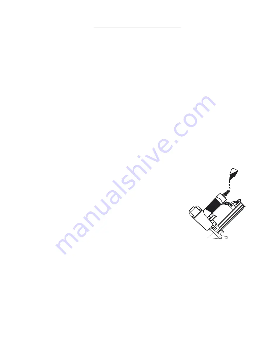
1. Frequent, but not excessive, lubrication is required for
best performance. Oil added through the airline connection
will lubricate internal parts. An automatic airline oilier is
recommended but oil may be added manually before every
operation or after about 1 hour of continuous use.
Only a few drops of oil at a time are necessary. Too much
oil will collect inside the tool and be blown out during the
exhaust cycle. ONLY USE PNEUMATIC TOOL OIL. Do not
use detergent oil or additives, as these lubricants will cause
accelerated wear to the seal in the tool.
7
Figure 3
2. Use a small amount of oil on all moving surface and pivots.
3. Dirt and water in the air supply are major causes of pneumatic tool wear. Use a fi lter/
oiler for better performance and longer life. The fi lter must have adequate fl ow capacity for
the specifi c application. Consult the manufacturer’s instructions for proper maintenance of
your fi lter.
4. Keep tools clean for better and safer performance. Use nonfl ammable cleaning
solutions only if necessary. CAUTION: Soaking the tool may damage O-ring and other
tool parts.
MAINTENANCE,
continued...
20FS Reassembly & Adjustments
(See fi gure 6.)
1) Install silver colored safety slide (75) into the silver foot (71)
2) Next install the gate (50) and gate plate (72) over the safety slide (75)
3) Install the two M4 screws (78) thru the front of the silver foot (71) thru the gate plate (72) thru the gate
(50) into the fi xed staple channel (51)
4) You will now need to align the center of the fi xed staple channel (51) with the center of the gate (50).
You can do this by eye and then tighten the two M4 screws (78). To test if the alignment is correct take a
half a stick of staples and slide them into the gate (50) making sure they slide freely and don’t get hung
up on the side of the gate (50) If the alignment is not correct loosen the two M4 screws (78) and re-do the
above procedure.
5) Tighten the two M4 screws (78) when the alignment is complete.
6) Note: Any time the two M4 and M5 screws (78) (80) are loosened or removed the channel alignment
adjustment must be done.
7) If the upper slide (44) of the staple channel was removed you can slide it on to the lower channel (51)
8) Now slide the staple channel assembly on to the drive blade, install the two M5 body screws (80) and
the two M4 screws (61) to the side of the staple channel rear support (58)
9) The black safety spring (25) can now be reinstalled which goes between the silver safety slide
extension (79) and the Safe Bracket Guider (24).
10) Reassemble the adjustable foot parts to the stapler & test. (76) (74) (73) (77)