background image


10

OPENING HOOD 

 
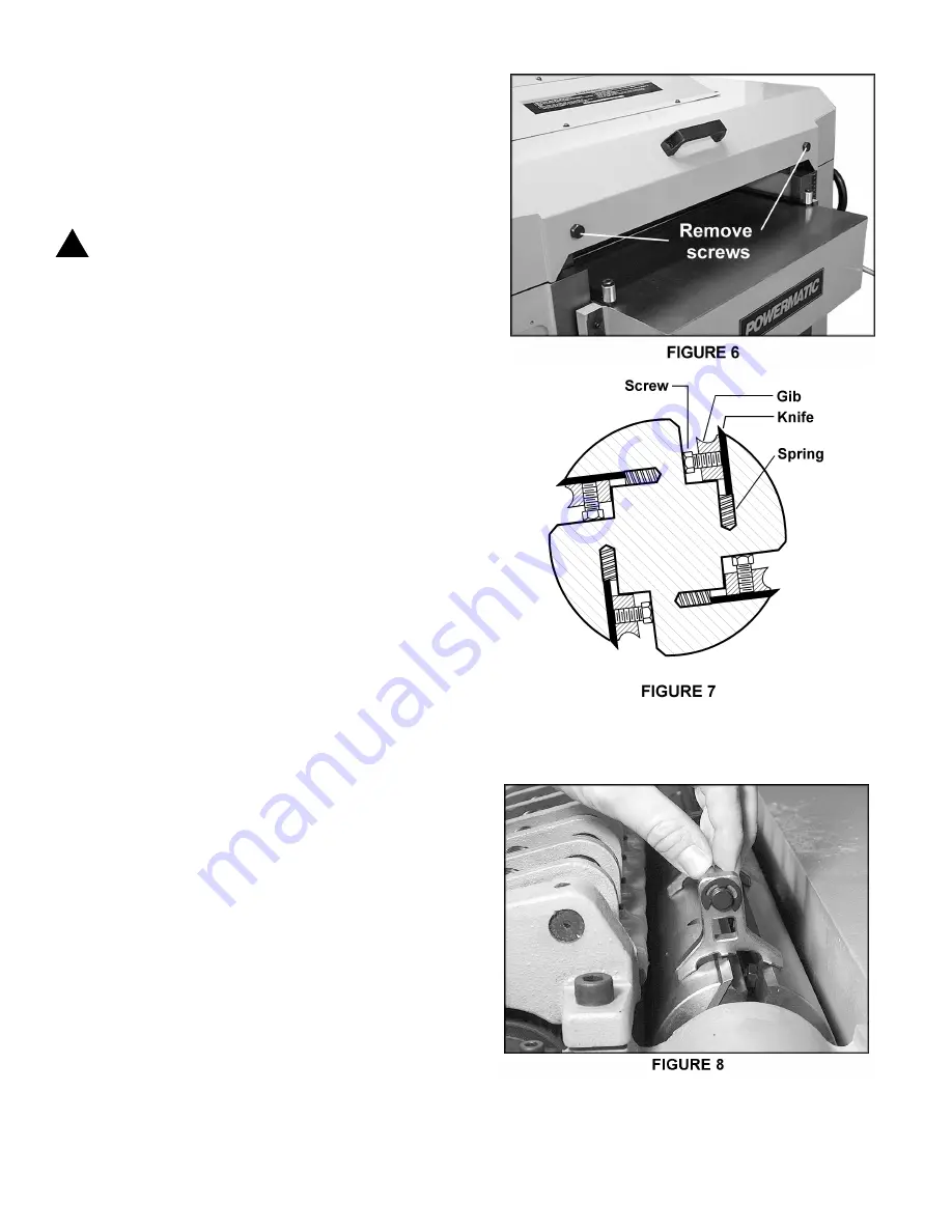
To open the hood for access to the cutterhead, remove 
the two hex screws with the 22mm wrench provided.  
See Figure 6. 
 

KNIFE INSTALLATION & ADJUSTMENT 


   CAUTION: Use care when placing hands near 
   knives as they are extremely sharp and can 
   cause severe cuts.   

 
Installing knives on a planer is an exacting process.  If 
the knives are not to be jointed and ground, end-to-end 
and knife-to-knife relationship must be held within .001" 
(.03mm) for accurate and smooth planing.  To help 
avoid cutterhead distortion in changing out a set of 
knives, remove and replace the knife in one slot before 
changing the next knife.  
Any knife adjustment or replacement should be done to 
all four knives at the same time.  Failure to do this may 
result in an out-of-balance cutterhead which can lead to 
bearing failure. 
 
1. 

Disconnect machine from power source. 

 
2. 

To remove knife, loosen the six hex head screws. 

See Figure 7. 
 
3.  The knife is spring loaded and will rise up in the 
slot.  Carefully remove knife from cutterhead by lifting 
straight out.  Remove gib and springs, and clean any 
dust, pitch or accumulated foreign matter from the slot 
and the gib. 
 
4.  Replace the springs and gib into the slot, then 
insert new knife and loosely snug the six hex head 
screws.   
 
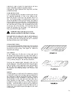
5.  Carefully place the knife-setting gauge until it 
contacts the cutterhead, as shown in Figure 8.  This will 
hold the high point of the knives to the proper height 
above the cutterhead (approximately 1/8” or 3.18mm).  
Use the gauge at both ends of the knife, then check the 
center section to be sure it is even.  If it is low, try 
backing off slightly on the center gib screw to allow 
blade to come up.  Gently tap blade down with piece of 
wood until it conforms to the gauge height.  Recheck the 
full length of the knife. 
 
NOTE:  If all knives have been removed, a new set 
must be installed with the gib screws lightly snugged 
down but not fully tightened.  All knives and gibs should 
be in place before tightening.  Locking one knife in 
without the others in position can cause cutterhead 
distortion.  The tightening process should proceed 
working from the center out on each knife and after 
locking all gib screws once, repeat the same sequence 
until all screws are equally tight.   

!

Содержание 201

Страница 1: ...22 PLANER Model 201 Instruction Manual Parts List M 0460224 800 274 6848 www powermatic com ...

Страница 2: ...wear and tear repair or alterations outside our facilities or to a lack of maintenance WMH TOOL GROUP LIMITS ALL IMPLIED WARRANTIES TO THE PERIOD SPECIFIED ABOVE FROM THE DATE THE PRODUCT WAS PURCHASED AT RETAIL EXCEPT AS STATED HEREIN ANY IMPLIED WARRANTIES OR MERCHANTIBILITY AND FITNESS ARE EXCLUDED SOME STATES DO NOT ALLOW LIMITATIONS ON HOW LONG THE IMPLIED WARRANTY LASTS SO THE ABOVE LIMITATI...

Страница 3: ...f Your Planer 11 Anti Kickback Fingers 11 Infeed Roll 11 Chipbreaker 12 Pressure Bar 12 Outfeed Roll 13 Table Rolls 13 Table Adjustments 14 Test Cutting Trouble Shooting 14 16 Maintenance 17 Lubrication 17 Trouble Shooting 18 20 Parts Lists Exploded Views Gearbox Assembly 21 22 Cutterhead Assembly 23 25 Top Cover Assembly 26 27 Column Assembly 28 29 Table Assembly 30 31 Base Assembly 32 34 Electri...

Страница 4: ... the work area is well lighted and that a proper exhaust system is used to minimize dust Powermatic recommends the use of anti skid floor strips on the floor area where the operator normally stands and that each machine s work area be marked off Provide adequate work space around the machine Avoid accidental starting Make certain motor switch is in off position before connecting power to the plane...

Страница 5: ... Doing so voids the warranty and Powermatic holds itself harmless from any injury that may result Machine adjustments Make all machine adjustments with power off except feed rate Job completion If the operator leaves the machine area for any reason the planer should be turned off and the cutterhead should come to a complete stop before his departure In addition if the operation is complete he shou...

Страница 6: ...y installed 3 Remove or fasten loose articles ofclothing such as neckties etc Containlong hair 4 Remove jewelry such as finger rings watches bracelets etc 5 Use approved safety glasses and or face shield toprotecteyes and use other personal safety equipment as required Do not wear gloves 6 Disconnect machine from power source before makingany adjustments or cleaning chips away from machine 7 Keep ...

Страница 7: ...utterhead diameter 3 1 4 Blade size 22 1 8 L x 7 8 W x 1 8 T Feed rate 20 30 FPM Overall dimensions 32 1 4 W x 50 H x 50 L Motor 7 5 HP 3 Ph 230V or 7 5 HP 3 Ph 460V or 7 5 HP 1 Ph 230V Shipping weight 1 197 lbs NOTE The above specifications were current at the time this manual was published but because of our policy of continuous improvement Powermatic reserves the right to change specifications ...

Страница 8: ...ents Alternately you can secure the machine to the floor by using lag screws through the holes in the base The machine area should be clean dry well ventilated and well lighted Since planers can create noise problems the site selection should be one which minimizes reverberant sound from walls ceilings and other equipment Electricals should be installed so that they are protected from damage and e...

Страница 9: ...ale C 3 Retighten lock knob B 4 The pointer D can be adjusted if the scale should ever need recalibrating FEED RATE ADJUSTMENT The Model 201 is equipped with selectable feed speed rolls that feed stock at 20 and 30 feet per minute To adjust speed turn lever shown in Figure 4 IMPORTANT Always change speeds while the machine is running BELT TENSION 1 Disconnect machine from power source 2 Remove low...

Страница 10: ...by lifting straight out Remove gib and springs and clean any dust pitch or accumulated foreign matter from the slot and the gib 4 Replace the springs and gib into the slot then insert new knife and loosely snug the six hex head screws 5 Carefully place the knife setting gauge until it contacts the cutterhead as shown in Figure 8 This will hold the high point of the knives to the proper height abov...

Страница 11: ...d before each day s use for pitch or gum buildup The fingers must operate freely and move independently for correct operation INFEED ROLL The function of the infeed roll is to feed the material into the machine It is a corrugated sectional roll with approximately 5 16 independent movement of each section to accomodate multiple board surfacing To provide proper drive it should be set so that the bo...

Страница 12: ...loaded sections mounted on a bar which swings concentric with the cutterhead The functions of the chipbreaker are to break chips into small pieces help avoid splintering of the wood help avoid board bounce on thinner boards to direct the flow of chips out of the machine and to permit multiple board surfacing The chipbreaker in its free position should be 1 32 8mm below the cutting arc of the knive...

Страница 13: ...ion of the stock on the table as it feeds through the machine It is not possible to give exact height setting of the table rolls because each type of wood behaves differently As a general rule however when planing rough stock the table rolls should be set high and when planing smooth stock the table rolls should be set low Height should should normally range between 005 to 015 The planer is equipp...

Страница 14: ... a bed and feed roll gauge or a wood gauge block to check parallelism at each end of the cutterhead 2 If the table is not parallel place the gauge at the end that needs to be raised Loosen the three socket head screws A beneath the table as shown in Figure 17 place a rod into one of the open holes B and turn the shaft C to raise the table until the gauge contacts the cutterhead Or the same effect ...

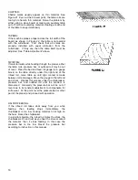
Страница 15: ... washboard finish down the full length of the board results from one knife being too high and forced to do all the cutting See Figure 18 Reset the high knife accordingly CLIP MARKS If clip marks occur 6 152 mm in from each end of the board the pressure bar is too high See Figure 19 Turn both right and left hand adjusting screws the same amount 1 4 turn clockwise or less and take another 1 16 1 58 ...

Страница 16: ...e the bed and feed roll gauge or a gauge block on the table directly under the right end of the infeed roll move table up until light contact is made between roll and gauge Move the gauge to the left end and check Repeat this process under the chipbreaker pressure bar and outfeed roll until the problem is discovered Generally the pressure bar will be out of level due to its constant adjustment to ...

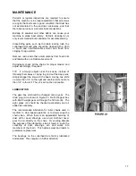
Страница 17: ...cks the knives instead of throwing them away or trying to grind out the deep nick simply stagger the knives in the head moving one knife no more than 1 4 to the right and another knife no more than 1 4 to the left The nick will not be noticeable LUBRICATION The gear box oil should be changed once a year The drain plug A is shown in Figure 23 Refill the gear box with 60 90 weight gear oil through t...

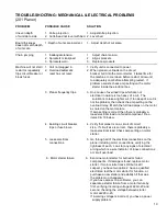
Страница 18: ... Dull knives 2 Sharpen knives Torn Grain 1 Too heavy a cut 1 Adjust proper depth of cut 2 Knives cutting against grain 2 Review planing for finish 3 Dull knives 3 Sharpen knives Rough Raised Grain 1 Dull knives 1 Sharpen knives 2 Too heavy a cut 2 Adjust proper depth of cut 3 Moisture content too high 3 Remove high moisture content from wood by drying Rounded glossy 1 Dull knives 1 Sharpen or repl...

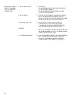
Страница 19: ...e problem then check the amp setting on the overload relay Match the full load amps on the motor as noted on the motor plate If amp setting is correct then there is probably a loose electrical lead or a failed component See items 9 10 below 4 Building circuit breaker 4 Verify that planer is on a circuit of correct trips or fuse blows size If circuit size is correct there is probably a loose electr...

Страница 20: ...to a quality electric motor repair shop and have it tested 9 Miswiring of the unit 9 Double check to make certain all electrical connections are correct and properly tight The electrical connections other than the motor are preassembled and tested at the factory Therefore the motor connections should be double checked as the highest probability for error If problems persist double check the factor...

Страница 21: ...ocket 1 19 6292789 Oil Plug PT1 4 19UNF 2 20 33 1051 00 1 Oil Seal TC20 x 40 x 7 1 21 6012051 Shaft 1 22 6012052 S Ring STW 25 1 23 6292745 Key 5 x 5 x 16 2 24 6012053 Shaft 1 25 6012054 Gear 1 26 6012055 Shaft 1 27 6012056 Gear 1 28 6012057 Gear Assembly 1 29 6012058 Set Screw M5 x 0 8P x 5Lg 1 30 6012059 Spring Pin 4mm x 25Lg 1 31 6012060 Shift Fork 1 32 6012061 Lever 1 33 6012062 E Ring ETW 12 ...

Страница 22: ...22 Gearbox Assembly Model 201 Planer ...

Страница 23: ...er 1 21 6012145 Belt A81 2 22 6012146 Cutterhead Pulley 1 23 6012147 Bushing 1 24 6012148 R Ring RTW 85 1 25 6012149 Ball Bearing 6209 2NSE 1 26 6012150 Set Screw M8 x 1 25P x 10Lg 8 27 6012151 Cutterhead Casting Left 1 28 6012152 Shaft 2 29 6012153 Shaft 2 30 6012154 Cutterhead 1 31 6012155 Ball Bearing 6007 2NSE 1 32 6012156 Socket Head Cap Screw M10 x 1 5P x 35Lg 6 33 6012157 Spring Washer 10 2...

Страница 24: ...to outfeed roll 1 61 6012275 Shaft 1 62 6012276 Idle Sprocket 1 63 6012277 Bracket 1 64 6012278 Shaft 1 65 6012279 Check Nut M8 x 1 25P 1 66 6012083 Flat Washer 8 5mm x 19 x 2T 1 67 6012280 Socket Head Cap Screw M8 x 1 25P x 50Lg 1 68 6012281 Spring 1 69 6012097 Hex Nut M8 x 1 25P 2 70 6012296 Spring 8 71 6012295 Knife Setting Gauge not shown 1 ...

Страница 25: ...25 Cutterhead Assembly Model 201 Planer ...

Страница 26: ... x 1 25P x 25Lg 10 7 6012185 Cast Hinge Half 4 8 6012079 Nut M10 x 1 5P 4 9 6012186 Socket Head Cap Screw M10 x 1 5P x 60Lg 2 10 6012187 Deflection Plate 1 11 6012188 Top Cover 1 12 6012189 Handle 1 13 6012067 Lock Washer 8 2mm x 15 4 6 14 6012097 Hex Nut M8 x 1 25P 10 15 6012190 Special Screw 2 16 6012191 Cylinder 2 17 6012192 Warning Label 1 18 6012282 Screw w Washer M6 x 1 0P x 10Lg 4 19 601228...

Страница 27: ...27 Top Cover Assembly Model 201 Planer ...

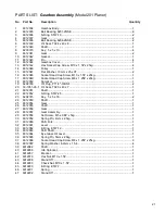
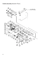
Страница 28: ... 6012205 Idler Assembly 1 22 6012206 Stand Off 2 23 6012207 Stop Switch 1 24 6012208 Start Switch 1 25 6012209 Ball Detent 6mm 1 26 6012210 Spring 1 27 6012211 Shifter Hub 1 28 6012212 Set Screw M6 x 1 0P x 12Lg 1 29 6012213 Shaft 1 30 6012214 Handle 1 31 6012087 Screw M5 x 0 8P x 10Lg 4 32 6012088 Cord Clip ACC 3 4 33 6012156 Socket Head Cap Screw M10 x 1 5P x 35Lg 14 34 6012215 Right Column 1 35...

Страница 29: ...29 Column Assembly Model 201 Planer ...

Страница 30: ...6 Socket Head Cap Screw M8 x 1 25P x 40Lg 6 21 6012048 Socket Head Cap Screw M10 x 1 5P x 20Lg 2 22 6012080 Flat Washer 10mm x 25 x 3T 2 23 6012098 Set Screw M5 x 0 8P x 5Lg 6 24 6012247 Special Screw 2 25 6012248 Linking Plate 3 26 6012249 Shaft 1 27 6012250 E Ring ETW 24 1 28 6012251 Set Screw M6 x 1 0P x 12Lg 1 29 6012252 Hub 1 30 6012213 Shaft 1 31 6012214 Handle 1 32 6293370 Key 5 x 5 x 10 3 ...

Страница 31: ...31 Table Assembly Model 201 Planer ...

Страница 32: ...2086 Bevel Gear 1 24 6012087 Screw M5 x 0 8P x 10Lg 4 25 6012088 Strain Relief Clip ACC 3 4 26 6012089 Pin 4 27 6012090 Base 1 28 6012091 Screw M6 x 1 0P x 10Lg 12 29 6012092 Cover 2 30 6012093 Special Hex Screw 4 31 6012094 Hex Nut M16 x 2 0 4 32 6012095 Foot 4 33 6012096 Set Screw M8 x 1 25P x 30Lg 1 34 6012097 Hex Nut M8 x 1 25 3 35 6012098 Set Screw M5 x 0 8P x 5Lg 2 36 6012099 Bevel Gear 1 37...

Страница 33: ...2T 8 59 6012121 Hex Nut M12 x 1 75 4 60 6012122 Flat Washer 13mm x 28 x 3T 4 61 6012123 Adjusting Bolt 2 62 6012124 Set Screw M8 x 1 25P x 12Lg 5 63 6012125 Spacer 2 64 6012126 Shaft 2 65 6012127 Motor Plate 1 66 6012128 Hex Screw M10 x 1 5P x 40Lg 4 67 6012129 Set Screw M8 x 1 25P x 20Lg 2 68 6012130 Flat Head Screw M6 x 1 0P x 20Lg 4 69 6012269 Terminal Cover 1 70 6012270 Screw 3 16 24NC x 1 4 1...

Страница 34: ...34 Base Assembly Model 201 Planer ...

Страница 35: ...35 ELECTRICAL SCHEMATIC Model 201 Planer 7 5HP 1Ph 230V ...

Страница 36: ...36 ELECTRICAL SCHEMATIC Model 201 Planer 7 5HP 3Ph 230V ...

Страница 37: ...37 ELECTRICAL SCHEMATIC Model 201 Planer 7 5HP 3Ph 460V ...

Страница 38: ...38 ...

Страница 39: ...d Serial Number of your machine available when you call will allow us to serve you quickly and accurately Locating the stock number of the part s required from your parts manual will also expedite your order Phone No 800 274 6848 Fax No 800 274 6840 If you are calling from Canada please call 800 238 4746 E mail powermatic wmhtoolgroup com Website www powermatic com ...

Страница 40: ...40 03 03 Rev A WMH Tool Group P O Box 1349 Auburn WA 98071 1349 Phone 800 274 6848 Fax 800 274 6840 E mail powermatic wmhtoolgroup com Website www powermatic com Powermatic ALL RIGHTS RESERVED ...

Отзывы: