5
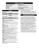
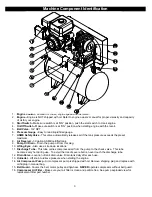
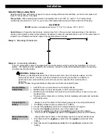
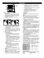
Breather
cap
Operation
INITIAL START-UP
1. Pump is shipped with oil. Remove the oil cap
and check pump oil level. Add SAE 30 non-
detergent pump oil (Part #4043), if necessary.
Hand tighten breather cap.
2. Turn pressure relief knob to engine start
position.
3. The engine is shipped without oil. Refer to the
engine manual for oil capacity and viscosity
recommendations.
4. Turn the gasoline line valve to the ON position.
5. For cold engine, move choke lever to full choke
position. To restart a warm engine, move choke
lever to half choke or to RUN position.
6. Start the engine:
A) Using electric start –
Turn the engine switch to the ON position.
Push and hold the START button until the
engine starts.
NOTE
: If the engine fails to start after 5
seconds, release the START button and wait
10 seconds before attempting to start again.
Cranking the electric starter for more than 5
seconds continuously can overheat and
damage the starter motor.
Release the START button when the engine
starts.
B) Using recoil start –
Turn the engine witch to the ON position.
Pull the starter grip lightly until you feel
resistance, then pull the starter cord out
briskly and rapidly.
Allow starter cord to return slowly.
7. When engine starts, move choke lever to RUN
position.
8. Once the engine has started, move the pressure
relief knob to the engine run position.
9.
CAUTION!
Unusual noise or vibration indicates
a problem. Do not continue to operate until you
identify and correct the source of the problem.
10.
CAUTION!
Do not attach air tools to open end
of the hose until start-up is completed and the
unit checks out OK.
11. Run the unit for 30 minutes, with ball valve open,
to break in pump parts.
12. Close the ball valve to shut off airflow. The
compressor is now ready for use.
13. After 50 hours of operation change the
compressor oil.
WARNING!
Never disconnect threaded joints with pressure in
the tank.
NOTE:
Reduce tank pressure below 10 psi, then
drain moisture from tank daily to avoid tank
corrosion. Drain moisture from tank by opening the
drain petcock located at the bottom of the tank.
COMPRESSOR LUBRICATION
CAUTION!
Do not operate without lubricant or with
inadequate lubricant. Use of compressor without
lubricant or inadequate lubricant voids all warranties.
Synthetic Lubricants
Synthetic lubricants are recommended after 50-hour
break-in. Compressor life is greatly increased with
the use of synthetic lubricants.
CAUTION!
If you will
be using synthetic lubricant, all downstream piping
material and system components must be
compatible.
Suitable
Viton
®
, Teflon
®
, Epoxy (Glass Filled), Oil Resistant
Alkyd, Fluorosilicone, Flourocarbon, Polysulfide, 2-Component
Urethane, Nylon, Delrin
®
, Celcon
®
, High Nitrile Rubber (Buna N.
NBR more than 36
Acrylonite), Polyurethane, Polyethylene,
Epichlorohydrin, Polyacrylate, Melamine, Polypropylene, Baked
Phenolics, Epoxy, Modified Alkyds
(
®
indicates trademark of DuPont Corporation)
Not Recommended
Neoprene, Natural Rubber, SBR Rubber, Acrylic Paint, Lacquer,
Varnish, Polystyrene, PVC, ABS, Polycarbonite, Cellulose
Acetate, Latex, EPR, Acrylics, Phenoxy, Polysulfones, Styrene
Acrylonitile (San), Butyl
Alternate Lubricants.
You may use petroleum-based lubricant
that is premium quality, does not contain detergents, contains
only anti-rust, anti-oxidation, and anti-foam agents as additives,
has a flashpoint of 440
°
F (227
°
C) or higher, and has a auto-
ignition point of 650
°
F (343
°
C) or higher.
See the petroleum lubricant viscosity table below. The table is
intended as a general guide only. Heavy duty operating conditions
require heavier viscosities. Refer specific operating conditions to
Powerhorse Product Support at 1-866-443-2576
Temperature around
Compressor
Viscosity Grade
ISO
SAE
Below 40
°
F (4
°
C)
60 20
40
°
F to 80
°
F
(4
°
C to 27
°
C)
100
30
80
°
F to 100
°
F
(27
°
C to 38
°
C)
150
40
Pump Capacities.
Refer to the following table for crankcase capacity
Item # Crankcase capacity
46851 48 oz
Engine start
Engine run


