background image


10HP - 20HP Scroll Enclosure Air Compressors 

Pg 2 

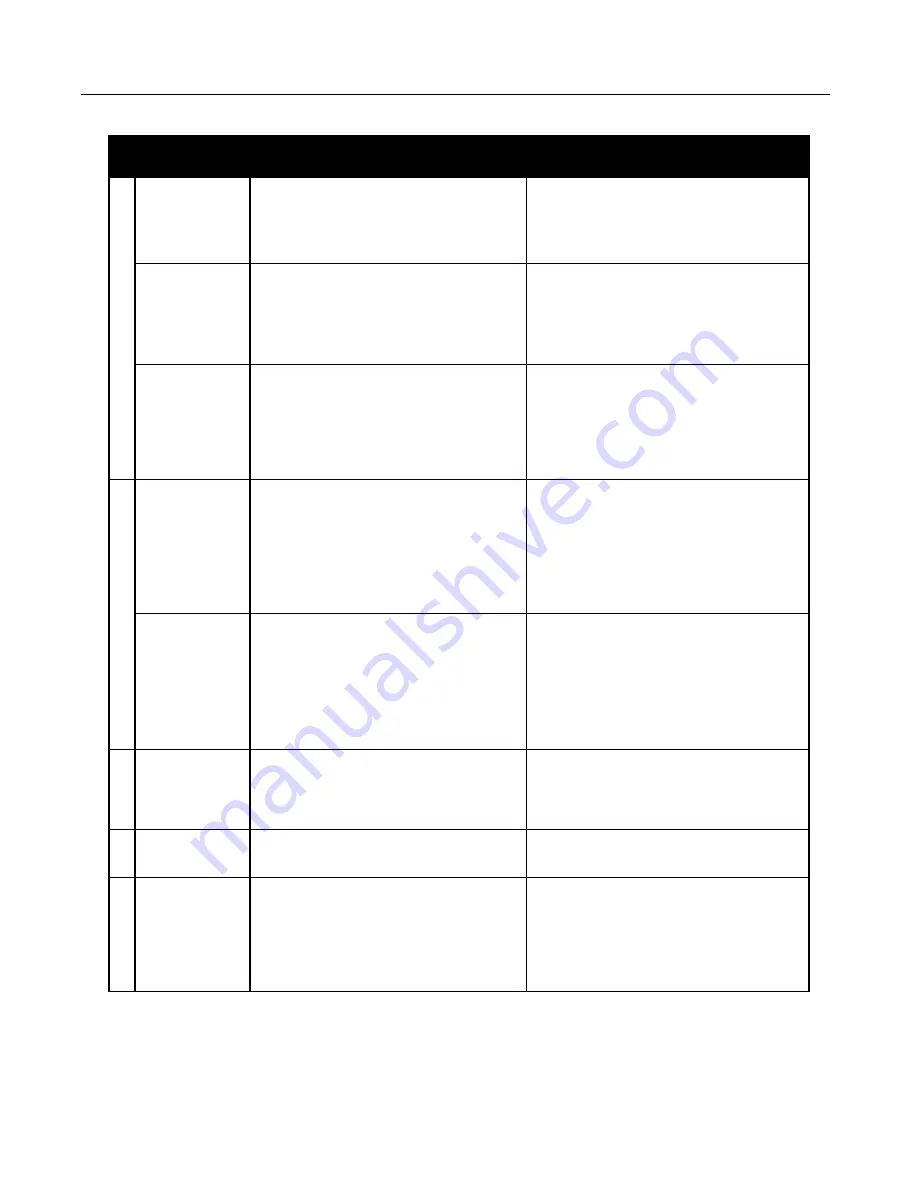
TROUBLESHOOTING GUIDE 


Problem 

Possible Cause 

Corrective Action 

Comp

re

ssor doe

s n

ot ope

ra

te 

No Display on the 
Operating Panel 

1. The electric source is not turned on                 
2. Transformer primary or secondary fuse open                                                                 
3. Electric source is not correctly connected      
4. Failure of display or PLC 

1. Turn on electric source                                     
2. Replace                                                             
3. Connect correctly                                                      
4. Inspect, repair or replace 

It does not operate 
despite displays 

1. Failure or wiring failure of magnetic starter    
2. Motor failure                                                    
3. Low voltage 

1. Inspect, repair or replace                                      
2. Inspect, repair or replace                                      
3. Check electric source capacity and the size of 
electric source cable and change to proper one 

Alarm Screen 
Active 

1. High temperature condition                            
2. Motor Overload condition                                             
3. High temperature indicated but unit is cool, 
has never been hot 

1.Allow to cool and reset, determine cause        
2. Reset motor overload, reset alarm and        
determine root cause of overload                         
3. A temperature switch may be disconnected or 
defective, check wiring 

Compressor starts but then st

ops
 

Alarm Screen 
High Temperature 

1. High ambient temperature or bad ventilation 
2. Clogging of aftercooler fins or intake wire 
screen                                                                  
3. Failure of ventilating fan                                 
4. Damage to intake hose                                    
5. Cooling passage of air end clogged                    
6. High exhaust pressure 

1.Improve installation environment & ventilation 
2. Clean                                                                         
3. Replace                                                             
4. Replace                                                                     
5. Inspect and clean                                                        
6. Inspect– control malfunction likely 

Alarm Screen 
Motor Overload 

1. Low voltage                      
2. Motor Failure                                                     
3. Air end failure                                                 
4. Loosened wiring screw                                      
5. High exhaust pressure                                             
6. Failure of thermal overload 

1. Check electric source capacity, size of electric 
source cable and change to proper one                        
2. Inspect, repair or replace                                           
3. Inspect, repair or replace                                           
4. Tighten                                                                            
5. Inspect - control failure likely                                  
6. Replace 


Exhaust pressure 
does not increase 

1. Air leaks from exhaust piping                                 
2. Air-end rotates backward                                  
3. Wrong pressure setting                                           
4. Clogged intake filter 

1. Inspect, repair                                                          
2. Change phases                                                             
3. Readjust                                                                
4. Clean or replace 


Safety valve    
activates 

1. Failure of safety valve                                       
2. Failure of pressure setting 

1. Replace                                                             
2. Inspect - control failure likely 


Abnormal sound 

1. Air-end rotates backward                                 
2. Air end failure                                                    
3. Belt slips                                                             
4. Motor failure                                                         
5. Cooling fan contacting frame                                
6. Loosened bolts 

1. Change phases                                                      
2. Inspect, repair or replace                                      
3. Check tension and readjust                                        
4. Inspect, repair or replace                                              
5. Inspect and repair                                                   
6. Inspect and tighten 

Содержание SED1007E

Страница 1: ...rbited around the fixed scroll the pockets formed by the meshed scrolls follow the spiral toward the center and diminish in size The moving scroll is prevented from rotating during this process so the 180 phase relationship of the scrolls is maintained The compressor s inlet is at the outer boundary of the scrolls The entering gas is trapped in two completely opposite gas pockets and compressed as...

Страница 2: ...mperature or bad ventilation 2 Clogging of aftercooler fins or intake wire screen 3 Failure of ventilating fan 4 Damage to intake hose 5 Cooling passage of air end clogged 6 High exhaust pressure 1 Improve installation environment ventilation 2 Clean 3 Replace 4 Replace 5 Inspect and clean 6 Inspect control malfunction likely Alarm Screen Motor Overload 1 Low voltage 2 Motor Failure 3 Air end fail...

Страница 3: ...afety Valve Confirm Operation Every 500 hours or less Pull ring to make sure not stuck or plugged Ventilation Fan Inspect Confirm ventilation air is exiting Motor Pulley Inspect Groove Make sure tight on shaft Replace if abnormal wear is detected Motor Inspect Replace if abnormal noise is detected Make sure electrical connections are secure Intake Hose Inspect Replace if damaged or deteriorating B...

Страница 4: ...se fitting and supply the proper volume of grease as indicated on the grease delivery chart See chart below Model 1st Time 2nd Time O S Bearing 7 times 6 times Pin Crank Bearing O S Side 7 times 7 times GREASE PIN CRANK BEARING Figure 6 1 Remove fan duct 2 Key 5 2 Remove the nuts and bolts and then the fixed scroll from the air end 3 Grease all three pin crank bearings as indicated on the grease d...

Страница 5: ...volute curving spiral See Figure 9 This is to be done for both FS and OS sets Use caution not to tear or distort lip 1 Insert new HP tip seal from the center section for OS or Orbit Scroll so that there will be no clearance at the tip start section See Figure 8 and 9 2 Insert so that new LP tip seal will contact closely with HP tip seal inside Scroll Groove Insert approximately half of the LP tip ...

Страница 6: ...al set reassemble Fixed Scroll set to the Orbit Scroll Tighten nuts and bolts temporarily and confirm if pump pulley rotates smoothly by hand and tighten them firmly Tightening torques are in the chart below First Second 175 in lbs 265 in lbs Bolt Torque NOTE Assemble so that dust seal and tip seal will not drop between Orbit Scroll set and Fixed Scroll set ...

Страница 7: ...Screen 5 V Belt 6 Intake Filter Element 7 Temp Switch 8 Pressure Sensor 9 Check Valve 10 Safety Valve 11 1 Magnetic Contactor 11 2 Motor Protector 12 1 Distribution Block 12 2 Distribution Block Cover 13 Inlet Plate 16 Inlet Gasket 14 Exhaust Fan 15 Control Transformer 19 Fuses 17 Braided Hose 18 Aftercooler Pg 7 ...

Страница 8: ...AV 2 3 4 2 2 Motor 575V MC303307AV 2 34 3 Motor Pulley PU009754AV 2 3 4 4 1 PLC PE000420AV 1 4 2 Touch Screen HMI panel PE000417AV 1 5 3VX belt BT012900AV 4 6 8 6 Intake filter element ST073907AV 1 7 Temp Switch AM003011AV AM003012AV AM003011AV AM003012AV AM003011AV AM003012AV 2 3 4 8 Pressure Sensor PE000450AV 1 9 Check Valve IP087700AV 2 3 4 10 Safety Valve V 215400AV V 215401AV V 215400AV V 215...

Страница 9: ...V 2 3 4 12 1 Distribution Block PE000622AV 1 12 2 Distribution Block Cover PE000640AV 1 13 Inlet Plate IP088400AV 2 3 4 14 Exhaust fan SM001301AV 2 3 4 15 1 Control Transformer 208 230 460V PS005850AV 1 15 2 Control Transformer 575V PS005839AV 1 16 Inlet Gasket IP088200AV 2 3 4 17 Braided Hose SM001501AV 2 3 4 18 Aftercooler SL300100AV 2 3 4 19 1 Primary Fuses 208V JP007710AV 2 19 2 Primary Fuses ...

Страница 10: ...0AV 1 4 Fan Duct 1 IP601400AV 1 5 Fan Duct 2 02519042 1 6 Fan Cover IP601700AV 1 7 Fan Dust Gasket 1 IP601900AV 1 8 Heat Insulation Pipe IP602000AV 1 9 Fan Duct Gasket 2 IP602400AV 1 10 Long Nipple 96647011 1 11 Dust Cap IP603500AV 1 12 Tip Seal Set 92832070 92832080 1 Grease Gun Kit IP616201AJ Grease Gun IP616101AJ Grease IP600000AV NOT SHOWN PARTS DIAGRAM LIST ...

Страница 11: ...NOTES 10HP 20HP Scroll Enclosure Air Compressors Pg 11 ...

Страница 12: ...roduct This warranty applies to the exchange of part s found to be defective by an Authorized Powerex Service Center only d Coverage The above mentioned warranty applies to Powerex manufactured units or systems only e Exceptions Notwithstanding anything contrary herein Powerex shall have no warranty obligations with respect to Products i that have not been installed in accordance with Powerex s wr...

Отзывы: