background image

www.powerbox-systems.com

11

4. SERVO MATCH FUNCTION

The Servo-Match function provides the facility for adjusting the centre po-
sition and end-points of the servos connected to the backer. If you have a 
model aircraft with more than one servo per control surface, this makes it 
possible to set up multiple servos to move to identical positions at identical 
times. Since this ensures that the servos do not work against each other, 
their effective life is increased, and more power is available to move the con-
trol surfaces; matched servos also draw lower current.

It is also possible to reverse the direction of rotation of individual servos. 
This function is useful if you wish to employ fewer channels at the trans-
mitter. For example, the right and left elevators, or the right and left landing 
flaps, can be controlled using only one radio channel. In models such as jets 
and warbirds, which by their nature have a large number of working sys-
tems, this feature can be very important, but it can also make transmitter 
programming much easier with other types of model.

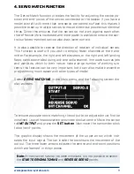
Select 

SERVO-MATCHING

 in the Main menu, and the following screen dis-

play appears:

To ensure accurate servo matching, the output to be adjusted must first be 
initialised. Leave the associated transmitter stick at centre. Move the cursor 
to 

INIT OUTPUT

 and press the 

SET button

. Now move the transmitter stick 

to both end-points.

The graphic display shows the movement of the upper arrow, which indi-
cates the input signal. The bar inside the box shows the movement of the 
output. The three lower arrows indicate the centre and end-point positions 
which are ‘learned’ in this process.

Note:

 if the channel has not yet been initialised, it is not possible to select 

the 

START SERVOMATCHING

 and 

REVERSE SERVO

 points.

Содержание cockpit

Страница 1: ...Instruction Manual PowErBox Cockpit PowErBox CompEtition PowErBox ProfEssionAl ...

Страница 2: ...s such as telemetry and the door sequencer assistant have been added These PowerBoxes are modern power supply systems which contain all the electronic components required for modern receivers servos and mo dels All the essential components for a secure power supply voltage ICs micro controllers and electronic circuits are duplicated The outstanding features of this High End power supply unit are a...

Страница 3: ...t processor for fast high resolution signal processing Four match channels each for two servos Accurate adjustment of all eight servos Double regulated output voltage for receivers and servos Can be connected to Jeti Futaba Spektrum HoTT and Multiplex down link channel bus systems Directtransmissionofbatteryvoltagesandcapacities notProfessional to the transmitter Separate voltage and capacity not ...

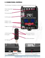
Страница 4: ...ial sockets and controls Door sequencer outputs Servo sockets OLED screen Battery input Battery 1 and 2 Receiver inputs Connector for Jeti Futaba Mul tiplex and HoTT Telemetrie Left socket for Spektrum telemetry Right SensorSwitch socket LEDs for power ON signal SET Button Switch buttons for Battery 1 and 2 LED for activation ...

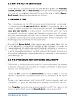
Страница 5: ...ted clearly on the case cover Connect the SensorSwitch to the appropriate red socket Note that the ribbon cable must run upwards In models subject to powerful vibration we recommend that you secure the ribbon cable at a minimum of one point in order to prevent the connector working loose and falling out Although this would have no effect on the switched state of the backer it would prevent you swi...

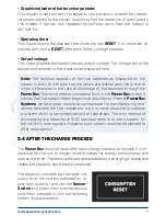
Страница 6: ...selected This means that the bar will extend right to the top of the box if the connected battery is fully charged assuming that you have set the correct battery type If the bar only fills the bottom third of the box then the corresponding battery is almost flat This indicator is supplemented by the residual capacity display Residual battery capacity Cockpit Competition only This display shows the...

Страница 7: ...the PowerBox This by no means indicates a fault in the PowerBox in fact it proves that the system features genuine redundancy Here at PowerBox Systems we take great trouble to compensate for manufacturing tole rances between the two regulators but it is never possible to produce a system which is completely devoid of tolerances The only method of discharging two batteries at 100 identical rates is...

Страница 8: ...ive method of programming which is a great advantage at the flying field as you will rarely need to consult the operating instructions This is the basic rule in programming buttons I and II are used to move the cursor or change values while the SET button is used to select or confirm your inputs The breadth of functions offered by the PowerBox Cockpit Competition and Professional is enormous but t...

Страница 9: ...t then press the SET button to select it cursor changes to a solid disc You can now alter the value using buttons I and II Once you have selected the desired value press the SET button to confirm it this saves stores the new value Select the menu point OK to return to the main menu Note the presence of a solid disc instead of a ring indicates that you are in a menu point It is possible to alter a ...

Страница 10: ...patible with a 7 4V supply Information on this subject can be found in the instructions for these components supplied by the manufacturers Compared with a direct unregulated voltage of 8 4V the advantage of a sta bilised 7 4V supply is that the voltage is always constant This means that the servos in your model always run at the same speed and with the same torque regardless of the manoeuvres you ...

Страница 11: ...ft landing flaps can be controlled using only one radio channel In models such as jets and warbirds which by their nature have a large number of working sys tems this feature can be very important but it can also make transmitter programming much easier with other types of model Select SERVO MATCHING in the Main menu and the following screen dis play appears To ensure accurate servo matching the o...

Страница 12: ...n You can now release the aileron stick the PowerBox maintains this positi on You now have both hands free and can adjust the position accurately with one hand using buttons I and II whilst checking the length matching of the disconnected ball link at the horn with the other hand Press the SET button again to conclude this adjustment Complete the set up procedure for the centre position and both e...

Страница 13: ...by moving the switch on your transmitter to both end points If you have set up a delay at the transmitter wait until the end point has been reached Use the SET button to select REVERSE SERVO A tick appears after the function and the left hand landing flap servo now operates in the correct direction Move the cursor to START SERVOMATCHING and press the SET button Use button I or II to adjust the cen...

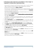
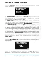
Страница 14: ...oor sequencer in accordance with the data you enter The Assistant guides you through the settings everything you need to do is described on the screen These printed instructions simply provide additional information which cannot be displayed on the PowerBox screen due to size limitations The recommended programming procedure is as follows first enter the ba sic settings using the SETUP ASSISTANT A...

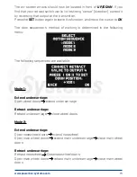
Страница 15: ... sequencer s method of working is determined in the following menu The following sequences are available Mode 1 Extend undercarriage Open wheel doors extend undercarriage Retract undercarriage Retract undercarriage close wheel doors Mode 2 Extend undercarriage Open nosewheel doors extend nosewheel Open main wheel doors extend main undercarriage close main wheel doors Retract undercarriage Retract ...

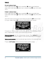
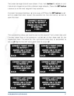
Страница 16: ...n wheel doors Move the cursor to the appropriate mode and press the SET button to con firm your choice Select OK to move on to the next screen display Connect your retract system valve to output 4 One of the following will now occur depending on the way your valve is programmed Valve is triggered and the undercarriage retracts Press button II on your SensorSwitch and hold it pressed in until the u...

Страница 17: ...nnect the nosewheel door servo to output 1 Press the SET button to clo se the nosewheel door repeat the procedure in the next set up screen to open the door The succeeding steps are used to set up the second front wheel door and the rear wheel doors the procedure is identical to that described for the nosewheel door The servo for the right hand wheel door is connected to output 2 that for the left...

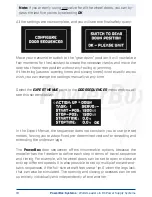
Страница 18: ...at any time Select the EXPERT MENUE point in the DOORSEQUENCER menu and you will see this screen display In the Expert Menue the sequencer does not constrain you to use pre set modes forcing you to adopt fixed pre determined vectors for retracting and extending the undercarriage The PowerBox door sequencer offers innumerable options because the modeller has the freedom to define each step in terms...

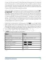
Страница 19: ... or desirable to alter the settings subsequently perhaps to fine tune the timing then this can be carried out using the menu points outlined below To help you arrive quickly at a satisfactory result the following section lists the door sequencer functions in detail The primary component of the procedure is the TASK which is self expla natory a task refers to the movement of a servo from its starti...

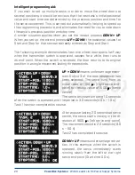
Страница 20: ... door opens half way when the transmitter switch is operated pauses for a while then runs to its end point When the switch is reversed the door returns to its original position in a single movement lasting three seconds UP DOWN means undercarriage exten sion Output 3 of the door sequencer has been selected The servo runs from its initial value of 1100 µs right servo end point to the stop value of ...

Страница 21: ...and extension of the undercarriage in the model should not exactly emulate that of the full size aircraft In other words you can give free rein to your imagination Note if you wish simply to switch servos or valves on or off you must always enter a time difference in the sequence as the door sequencer needs a small amount of time to carry out its calculations The following is an example for a retr...

Страница 22: ... but it also creates a danger if you accidentally include a control channel e g elevator in your pro gramming the control channel will then be switched off when you retract the undercarriage after the model takes off This will usually result in loss of the model 7 FRAME RATE What does frame rate mean This value indicates the time interval at which the servo signal is refreshed Modern digital servo...

Страница 23: ...try output to the receiver s sensor input using a standard commercial Uni patch lead The voltage and residual capacity of both batteries are now available at the transmitter Spektrum Connect the four pin Spektrum Telemetry output to the TM1000 and at the same time bind the TM1000 and the connected satellites to the transmitter Activate the PowerBox Telemetry display at your transmitter The voltage...

Страница 24: ... avoid accidental erasure of data If you confirm this query the settings are permanently era sed and cannot be restored The PC CONTROL option permits the Competition Cockpit Professional to be connected to a PC a tablet or a mobile telephone In this way you can load updates into the PowerBox to ensure that it constantly reflects the latest state of development The following methods are available a...

Страница 25: ...ssing through the full battery voltage This means that the servos and receiver are being opera ted on an excessive voltage which could lead to failures in the longer term This malfunction usually occurs after a reversed polarity connection One battery is plugged in but not switched on The second battery is plug ged in and switched on The screen displays the message REGULATOR MALFUNCTION This does ...

Страница 26: ...8 ms 21 ms frame rate Screen OLED 128 x 64 pixels graphic Servo sockets Professional 12 sockets 8 channels Competition 18 sockets 12 channels Cockpit 21 sockets 11 channels Temperature range 30 C to 75 C Weight 115 g SensorSwitch 15 g EMV approval EN 55014 1 2006 CE approval 2004 108 EG WEEE Reg No DE 639 766 11 This battery backer fulfils the EMV protective requirements EN 55014 1 2006 with certi...

Страница 27: ...www powerbox systems com 27 12 DIMENSIONS ...

Страница 28: ...rs and have now established a Support Forum which covers all queries relating to our products This helps us considerably as we no longer have to answer fre quently asked questions again and again At the same time it gives you the opportunity to obtain assistance all round the clock and even at weekends The answers come from the PowerBox team which gu arantees that the answers are correct Please us...

Страница 29: ...valid if damage is due to mishandling or incorrect use e g reversed polarity excessive voltage or damp The same applies to defects caused by heavy wear or excessive vibration Any further claims e g for consequent damages will not be entertained 16 LIABILITY EXCLUSION We are not in a position to ensure that you install and operate this battery backer correctly nor that you maintain the entire radio...

Страница 30: ...PowerBox Systems GmbH certificated according to DIN EN ISO 9001 2008 Ludwig Auer Straße 5 D 86609 Donauwoerth Germany 49 906 99 99 9 200 49 906 22 45 9 www powerbox systems com 10 2017 ...

Отзывы: