background image

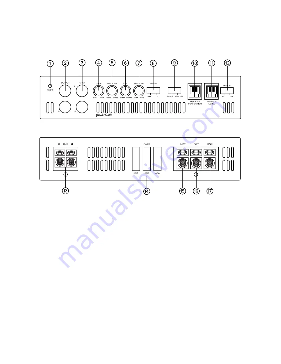
CONTROL PANEL LAYOUT

1. POWER/STATUS Indicator

The BLUE L.E.D. lights up when the power is on. This L.E.D. turns RED constantly or flashes when the built-in 
protection circuitry is activated. This indicates a problem with the system in relation to the amplifier (see 
Troubleshooting Tips page 21).

2. LINE OUT (RCA) Jacks

RCA style pass through output jacks allow for a signal to be sent to other amplifiers in a daisy-chain configu-
ration. Only one Remote Bass Control can be used when multiple bass amplifiers are connected.

3. LINE IN (RCA) Jacks

These RCA style input jacks are for use with source units that have RCA line level outputs. A source unit with a 
minimum output of 200mV is required for proper operation.  However, this input will accept levels up to 6Vrms.

Fig.2 Panel Layout

Содержание ASA3-1000.1D

Страница 1: ...your new amplifier Should your PowerBass Auto Sound mobile amplifier ever require service you will need to have the original dated receipt ASA3 600 1D ASA3 1000 1D ASA3 1500 1D 1 OHM STABLE DESIGN Min...

Страница 2: ...these models are designed specifically for low frequencies and are intended only to power subwoofers It is important that you closely follow the wiring instructions contained in this Owners Manual so...

Страница 3: ...1D only Dual Link Power Doubling Circuit Amp to Amp Bridged at 2 ohm minimum INSTALLATION EXPERIENCE Installation of PowerBass mobile amplifiers requires detailed knowledge of electronics wiring and...

Страница 4: ...fabric from hole locations before drilling or cutting When running power cables through sheet metal be sure to use grommets to properly insulate the metal edges from the wire insulation If possible us...

Страница 5: ...rear seat For alternate installation locations please consult your authorized PowerBass Dealer NOTE Do not use a drill with driver bit to mount the amplifier Excessive force could cause the plastic mo...

Страница 6: ...21 2 LINE OUT RCA Jacks RCA style pass through output jacks allow for a signal to be sent to other amplifiers in a daisy chain configu ration Only one Remote Bass Control can be used when multiple ba...

Страница 7: ...by bringing the low frequency from the rear of the vehicle to the front 9 BRIDGED Switch Two like amplifiers can be connected together and bridged into a single 2 ohm min load The level and fre quenc...

Страница 8: ...0A x 3 ASA3 1500 1D 40A x 4 15 BATT Power Input Terminal This terminal is the main power input for the amplifier and must be connected directly to the positive terminal of the car battery see Power Ca...

Страница 9: ...art any wiring work The bat tery of your car audio system must be disconnected until the entire wiring installation is completed Your PowerBass Autosound Class D amp will draw large levels of current...

Страница 10: ...nding your amplifier locate a metal area close to the amplifier that is good source of ground preferable the floor pan Once again investigate the area you wish to use for electrical wires vacuum lines...

Страница 11: ...crew terminal marked REM on the amplifier Insert the stripped bare portion of the wire into the terminal and tighten the screw securely FUSE REQUIREMENTS While the panel on your PowerBass amplifier in...

Страница 12: ...bles Car environments are notorious for poorly insulated wires This means that hiss engine noise and fan noise can easily be picked up through RCA cables if run incorrectly Make sure that the cables f...

Страница 13: ...you with damaged speaker and or a damaged amplifierr LPF Low Pass Filter Adjustment The crossover frequency adjustment filters out frequencies that you don t want your speaker s to reproduce Using th...

Страница 14: ...Connection Your PowerBass Autosound Class D amp includes a Remote Level control module It uses standard telephone wire and telephone RJ 45 connectors To connect the Remote Level Control to the amplifi...

Страница 15: ...nd using insulated speaker terminals not supplied or by soldering the connection to the speaker Be certain to maintain correct polarity throughout the system Make sure the speaker connections are posi...

Страница 16: ...bwoofer 1 4 ohm Fig 12 Two 4 ohm Subwoofers with Single Voice Coil Speaker Output Configurations 1 A SINGLE VOICE COIL SUBWOOFER SPEAKER 2 TWO SINGLE VOICE COIL SUBWOOFER SPEAKERS Note Don t connect s...

Страница 17: ...nimum Impedance Load is 1 Ohm Unless you are bridging two ASA3 amplifiers in which case min load is 2 ohms Maintaining proper impedance is critical when wiring the Class D model amplifiers Improper wi...

Страница 18: ...the BRIDGED switch and wiring the two amplifiers as follows Be sure to set the BRIDGED switch on the first amplifier to MASTER and set the second amplifier to SLAVE Use the supplied RJ 45 cable to co...

Страница 19: ...ystem will not function properly and damage to the amplifiers may result Total impedance of speakers must be over 2 ohms If the impedance drops under 2 ohms critical damage to the amplifier will occur...

Страница 20: ...ur website at www powerbassusa com PERSONAL NOTES Name ______________________________________________________________ Date Purchased ______________________________________________________ Dealer _____...

Страница 21: ...air flow around the amplifier Voltage protection engaged Voltage to the amp is not within the 9 17 VDC operating range Have the battery charging system inspected Short circuit protection is engaged Ch...

Страница 22: ...Hz 150 Hz 1dB Crossover Low Pass Filter 40Hz 150 Hz Crossover Slope 12dB Octave Sub Sonic Filter 15Hz 50Hz Bass EQ at 45Hz 0 18 dB Input Gain Control 0 2V 6 0V Low Level Input Impedance 22K Ohms Dampi...

Страница 23: ...d damage or exposure to excessive heat Attempted repairs or alterations of any nature Product that has not been installed according to this owners manual Any implied warranties including warranties of...

Страница 24: ...PowerBass Autosound A division of PowerBass USA Inc 2133 S Green Privado Ontario CA 91761 Tel 909 923 3868 Fax 909 923 8048 www powerbassusa com...

Отзывы: