background image

Power-Flo Pumps & Systems • 877-24PUMPS • www.powerfl opumps.com

12

Outer Seal (Single & Double) -

 Handle 

seal parts with care. Remove c-clip (43), 
seal (33) spring and rotating member 
from shaft. Examine all seal parts. Inspect 
contact faces for signs of uneven wear 
tracks on stationary, chips and scratches 
on either seal face. 

DO NOT interchange 

seal components, replace the entire 
shaft seal (33).

Seal Plate (Double) -

 Remove cap screws 

(52) and washers (11) from seal plate (51). 
Remove seal plate (51) and square ring 
(24) from intermediate coupling (21B). 
With fl at screwdriver, press out seal (33) 
stationary member. Inspect square ring 
(24) for cuts or abrasions.

Checking Capacitors - 

Loosen gland 

nut (3) and remove cap screws (22) and 
washers (11) from upper housing (19). 
Check motor capacitors (14) & (16) with 
an Ohm meter by placing a screwdriver 
across both terminals and to ground the 
capacitor then remove.  Connect Ohm 
meter, set on high scale to terminals. If 
needle moves to infi nity (∞) then drifts 
back, the capacitor is good. If needle does 
not move or moves to infi nity (∞) and 
does not drift back, replace the capacitor.

Motor -

 Remove wires from terminal 

block (37) and remove cable assembly 
(3) and upper housing (19). Remove 
pipe plug (4) from housing (15) and 
drain oil if not already done so. Position 
pump upright using blocks or pvc pipe 
to avoid resting pump on the shaft. 
Remove retaining ring (38). Using a 1/4-20 
bolt, thread bolt into the center of the 
terminal block (37) and pull straight up to 
removing it and o-ring (12). Disconnect all 
wires, noting where each was connected. 
There are numbers next to the pins on the 
bottom of block, use these for reference.
Remove cap screws (35) and lockwashers 
(11) from motor housing (15). Vertically 
lift motor housing (15) from intermediate 
coupling (21) along with square ring (20),  
replace if cut or damaged. Remove stator 
bolts and carefully remove stator housing 
from rotor. Pull rotor out with bearing (18).

Inspect motor winding for shorts and 
check resistance values. Check rotor for 
wear. If rotor or the stator windings are 
defective, the complete motor must be 
replaced.

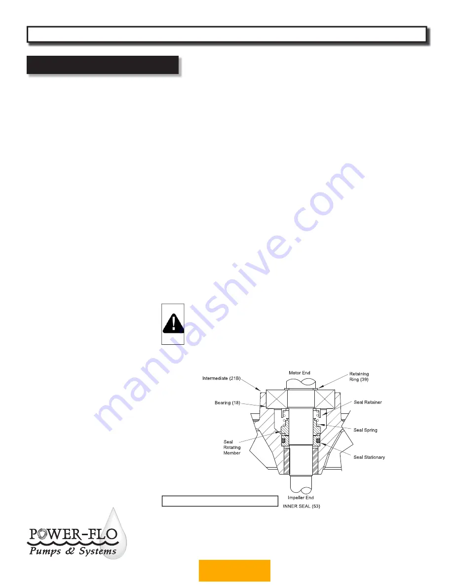
Inner Seal (Double) -

 Remove seal (53) 

rotating member and spring from rotor 
shaft.  Press stationary from intermediate 
(21B) with fl at screwdriver. Examine all 
seal parts. Inspect contact faces for signs 
of uneven wear tracks on stationary, 
chips and scratches on either seal face. 

DO NOT interchange seal components, 
replace the entire shaft seal (53).

Bearings -

 Remove retaining ring (39)

from shaft. Using a wheel puller or arbor 
press remove bearing (18) from shaft. 
Remove upper motor bearing from shaft 
with a bearing puller. (See Figure 5).

On Double Seal Units

, Check sleeve 

bearing (23) for excessive wear, if 
replacement is required, press sleeve from 
intermediate coupling (21).

 IMPORTANT! - All parts must be
 clean before reassembly. 
 Handle seal parts with extreme 
 care. DO NOT damage lapped 
 surfaces.

Reassembly

Bearing -

 Be careful not to damage the 

rotor shaft when replacing bearing. Using 
an arbor press, hold the rotor and press 
the upper bearing on the rotor shaft, 
applying force to the inner race of the 
bearing only. Replace upper retaing ring 
onto rotor shaft. In the same manner 
replace lower bearing (18) onto rotor 
shaft. Place lower retaining ring (39) onto 
shaft.

Inner Seal (Double) -

 Clean and oil seal 

cavity in intermediate coupling (21B). 
Lightly oil 

(Do not use grease)

 outer 

surface of stationary member. Press 
seal’s (53) stationary member firmly into 
intermediate coupling (21B), using a seal 
tool or pipe. Nothing should come in 
contact with the seal face except the seal 
tool. Be sure the stationary is in straight. 
Place seal’s (53) retaining ring and spring 
over shaft until seated on shaft shoulder. 
Slide a bullet tool over rotor shaft 
threads.

Lightly oil 

(Do not use grease)

 shaft, 

bullet, and inner surface of bellows on 
rotating member, with fi nished end away 
from motor, slide rotating member over 
bullet and onto shaft until it engages 
spring. Make sure spring is seated in 
retaining ring and spring is lined up on 
rotating member and not cocked or 
resting on bellows tail. (See Figure 5)

Service

PFGPC - 2HP 


        Submersible Grinder Pumps

Figure 5 (Double Seal Unit Shown)

BACK TO INDEX

Содержание PFGPC2002HH Series

Страница 1: ...TALLATION SERVICE PARTS MANUAL Power Flo Pumps Systems 877 24PUMPS www powerflopumps com Series PFGPC2002HVS HHS PFGPC2002HVSA HHSA PFGPC2022HVS HHS PFGPC2022HVSA HHSA Single Seal 2 HP 3450 RPM 60 Hz...

Страница 2: ...toys utensils etc Sanitary Napkins or Tampons Diapers Rags Disposable Wipes or Cloth Medications Flammable Material Oil or Grease Strong Chemicals Gasoline Risk of electric shock To reduce risk of el...

Страница 3: ...Steel CUTTER Stainless Steel SHAFT Stainless Steel SQUARE RINGS Buna N HARDWARE Stainless Steel PAINT Powder Coated Industrial Grade SEAL Single Mechanical Carbon Ceramic Buna N UPPER BEARING Single r...

Страница 4: ...3450 17 0 53 0 F SOW 12 3 67 PFGPC2022HHSA 2 60 230 1 3450 15 0 53 8 H SOW 12 3 67 Specifications Dimensions MODEL HP Volts Ph BREAKER SIZE VOLTAGE RELAY START CAPACITOR RUN CAPACITOR High Volume PFG...

Страница 5: ...12 Vane Vortex Bronze SHREDDING RING Stainless Steel CUTTER Stainless Steel SHAFT Stainless Steel SQUARE RINGS Buna N HARDWARE Stainless Steel PAINT Powder Coated Industrial Grade POWER CORD 20 ft Cus...

Страница 6: ...ns Dimensions MODEL HP Volts Ph BREAKER SIZE VOLTAGE RELAY START CAPACITOR RUN CAPACITOR High Volume PFGPC2002HV 2 200 1 30 Amp internal MARS 169 internal 150 mfd 250v internal 20 mfd 450v PFGPC2022HV...

Страница 7: ...Power Flo Pumps Systems 877 24PUMPS www powerflopumps com 7 Performance PFGPC HH HHS 2HP Submersible Grinder Pumps BACK TO INDEX...

Страница 8: ...Power Flo Pumps Systems 877 24PUMPS www powerflopumps com 8 Performance PFGPC HV HVS 2HP Submersible Grinder Pumps BACK TO INDEX...

Страница 9: ...Discharge piping should be as short as possible and sized no smaller than the pump discharge Do not reduce the discharge pipe size below that which is provided on the pump Both a check valve and a shu...

Страница 10: ...chambers for oil level and contamination b Inspect impeller and body for excessive build up or clogging c Inspect motor and bearings d Inspect seal for wear or leakage Servicing NOTE Item numbers in...

Страница 11: ...te for oil expansion Apply pipe thread compound to threads of pipe plug 4 then assemble to motor housing 15 Check that o ring 24 is in place and does not need to be replaced Reassemble upper housing t...

Страница 12: ...k rotor for wear If rotor or the stator windings are defective the complete motor must be replaced Inner Seal Double Remove seal 53 rotating member and spring from rotor shaft Press stationary from in...

Страница 13: ...ith lockwashers 11 into seal plate and torque to 6 5 ft lbs Outer Seal Single Double Clean and oil stationary seal cavity in bearing bracket 21A on Single Seal or 51 seal plate on Double Seal Slide se...

Страница 14: ...e on threads and place into shaft and tighten Upper Housing Capacitors Assemble capacitors 14 16 and relay 13 to housing Place o ring 24 onto motor housing 15 Assemble gland nut 3 friction ring 46 and...

Страница 15: ...lopumps com 15 Figure 10 Repair Parts For Repair Part Please supply Model Number and MFG Date as shown on Name Plate and Part Description and Part Number as shown on Parts List PFGPC HVS HHS 2HP Singl...

Страница 16: ...flopumps com 16 Repair Parts For Repair Part Please supply Model Number and MFG Date as shown on Name Plate and Part Description and Part Number as shown on Parts List PFGPC HV HH 2HP Double Seal Subm...

Страница 17: ...4 200 Volt 1 Ph PF081200S10 Motor Double Seal 230 volt 1 Ph PF110397BG 200 volt 1 Ph PF081200S06 18 1 6 Lower Bearing PF10 36 E4 19 1 Upper Housing PF105196CAP 20 1 6 Square Ring PF074498 21A 1 Bearin...

Страница 18: ...r Clamp 7mm PF033459 46 2 Friction ring PF051450 47 1 Bronze Insert Double Seal Only 48 1 Pipe Plug 1 4 NPT Double Seal Only 49 4 Stud 5 16 18 x 2 1 4 Lg Stainless Double Seal Only 50 4 Hex Nut 5 16 1...

Страница 19: ...equired Consult the factory Disconnect unit electrically Remove the pump from the basin Detach the pump base and clean the area around the impeller Rotate impeller by hand Reassemble and reinstall Pum...

Страница 20: ...ained in accordance with Manufacturer s installation instructions that has been exposed to outside substances including but not limited to the following sand gravel cement mud tar hydrocarbons hydroca...

Отзывы: