background image

6

ASSEMBLY

Your new tractor has been assembled at the factory with exception of those parts left unassembled for shipping purposes.  

To ensure safe and proper operation of your tractor all parts and hardware you assemble must be tightened securely.  Use 

the correct tools as necessary to insure proper tightness.

BEFORE REMOVING TRACTOR FROM 

SKID

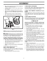
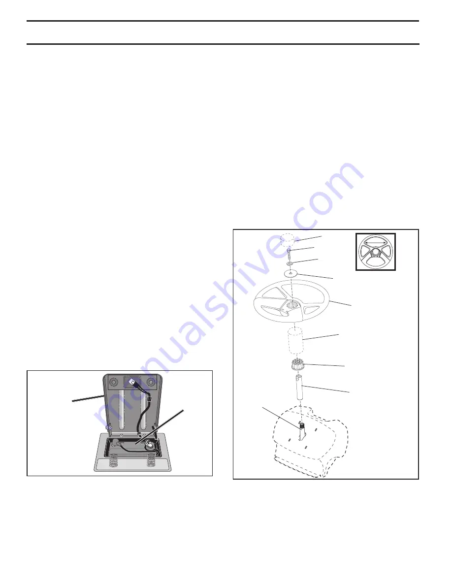
ATTACH STEERING WHEEL (See Fig. 2)

ASSEMBLE EXTENSION SHAFT AND BOOT

•  Slide extension shaft onto lower steering shaft.  

Fig. 2

TOOLS REQUIRED FOR ASSEMBLY

A socket wrench set will make assembly easier.  Stan dard 

wrench sizes are listed.
(1)  5/16" wrench 


Utility knife

(2)  7/16" wrenches 


Tire pressure gauge

(2) 1/2" wrenches 


Pliers

(1) 9/16" wrench

When right or left hand is mentioned in this man ual, it means 

when you are in the operating po si tion (seated be hind the 

steer ing wheel).

TO REMOVE TRACTOR FROM 

CAR TON

UNPACK CARTON

•  Remove all accessible loose parts and parts cartons  

from carton.

•  Cut along dotted lines on all four panels of carton. 

Remove end panels and lay side panels flat.

•  Check for any additional loose parts or cartons and 

remove.

INSTALL SEAT (See Fig. 3)

Adjust seat before tightening adjustment knob.
•  Remove adjustment knob and flat washer securing 

seat to cardboard packing and set aside for assembly 

of seat to tractor.

• 

Pivot seat upward and remove from the cardboard pack-

ing. Remove the cardboard packing and discard.

TO CHECK BATTERY (See Fig. 1)

•  Lift seat to raised position.

NOTE:

 If this battery is put into service after month and 

year indicated on label (label is located between terminals) 

charge battery for minimum of one hour at 6-10 amps. 

(See "BATTERY" in Maintenance  section of this manual 

for charging instructions).
•  For battery and battery cable installation see "RE-

PLACING BATTERY" in the "Service and Adjustments" 

section in this manual.

02602

SEAT

LABEL

Fig. 1

02819

LOWER

STEERING 

SHAFT

STEERING 

BOOT

EXTENSION 

SHAFT

STEERING 

WHEEL

INSERT

ADAPTER

BOLT

LARGE FLAT 

WASHER

LOCK 

WASHER

•  Place tabs of steering boot over tab slots in dash and 

push down to secure.

INSTALL STEERING WHEEL

• 

Position front wheels of the tractor so they are pointing 

straight forward.

•  Remove steering wheel adapter from steering wheel 

and slide adapter onto steer ing shaft ex ten sion.

•  Position steering wheel so cross bars are hor i zon tal 

(left to right) and slide inside boot and onto adapt er.

• 

Assemble large flat washer, 5/16 lock washer, 5/16 hex 

bolt and tighten se cure ly.

•  Snap steering wheel insert into center of steer ing 

wheel.

•  Remove protective materials from trac tor hood and 

grill.

IMPORTANT:  

CHECK FOR AND REMOVE ANY STAPLES IN 

SKID THAT MAY PUNCTURE TIRES WHERE TRACTOR IS TO 

ROLL OFF SKID.

Содержание 438511

Страница 1: ...YE PROTECTION DURING OPERATION Visit our website www poulan com WARNING Read this Manual and follow all Warnings and Safety Instructions Failure to do so can result in serious injury IMPORTANT MANUAL Do Not Throw Away 5000 438511 09 16 10 TH Printed in the U S A ...

Страница 2: ...op engine and remove keys before dismounting Disengage blades when not mowing Shut off engine and wait for all parts to come to a complete stop before cleaning the machine removing the grass catcher or unclogging the discharge chute Operate machine only in daylight or good artificial light Do not operate the machine while under the influence of alcohol or drugs Watch for traffic when operating nea...

Страница 3: ...ch towed equipment except at the hitch point Follow the manufacturer s recommendation for weight limits for towed equipment and towing on slopes Never allow children or others in or on towed equipment On slopes the weight of the towed equipment may cause loss of traction and loss of control Travel slowly and allow extra distance to stop V SERVICE SAFE HANDLING OF GASOLINE To avoid personal injury ...

Страница 4: ... pleasecontactyournearestauthorizedservicecenter department We have competent well trained technicians and the proper tools to service or repair this tractor Please read and retain this manual The instructions will enable you to assemble and maintain your tractor properly Always observe the SAFETY RULES CUSTOMER RESPONSIBILITIES Read and observe the safety rules Follow a regular schedule in mainta...

Страница 5: ...eel 1 Washer 1 Knob Steering Wheel Insert Seat 1 Seat Steering Boot Steering Extension Shaft Steering Wheel Adapter Keys 2 Keys Slope Sheet 1 Oil Drain Tube For Future Use 1 Hex Bolt 5 16 18 x 4 1 5 16 Lock Washer 1 Large Flat Washer ...

Страница 6: ...d packing and set aside for assembly of seat to tractor Pivotseatupwardandremovefromthecardboardpack ing Remove the cardboard packing and discard TO CHECK BATTERY See Fig 1 Lift seat to raised position NOTE If this battery is put into service after month and year indicated on label label is located between terminals charge battery for minimum of one hour at 6 10 amps See BATTERY in Maintenance sec...

Страница 7: ...for best cutting results Tires must be properly inflated for leveling Check mower and drive belts Be sure they are routed properly around pulleys and inside all belt keepers Check wiring See that all connections are still secure and wires are properly clamped WHILE LEARNING HOW TO USE YOUR TRACTOR PAY EXTRA ATTENTION TO THE FOLLOWING IMPORTANT ITEMS Engine oil is at proper level Fuel tank is fille...

Страница 8: ...r death The safety alert symbol is used to identify safety inform ation about hazards which can result in death serious injury and or property damage DANGER indicates a hazard which if not avoided will result in death or serious injury WARNING indicates a hazard which if not avoided could result in death or serious injury CAUTION indicates a hazard which if not avoided might result in minor or mod...

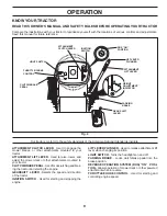
Страница 9: ...ects the speed and direction of the tractor IGNITION SWITCH Used for starting and stopping the engine Our tractors conform to the safety standards of the American National Standards Institute Fig 4 PARKING BRAKE CLUTCH BRAKE PEDAL THROTTLE CHOKE CONTROL GEAR SHIFT LEVER ATTACHMENT LIFT LEVER LIFT LEVER PLUNGER IGNITION SWITCH ATTACHMENT CLUTCH LEVER ROS ON POSITION HEIGHT ADJUSTMENT INDICATOR LIGH...

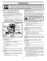
Страница 10: ...ght HOW TO USE YOUR TRACTOR TO SET PARKING BRAKE See Fig 5 Your tractor is equipped with an operator presence sens ing switch When engine is running any attempt by the operator to leave the seat without first setting the parking brake will shut off the engine Depress clutch brake pedal into full BRAKE position and hold Place parking brake lever in ENGAGED position and release pressure from clutch ...

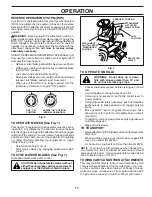
Страница 11: ...ithenginerunning turnignitionkeycounterclockwise to ROS ON position Look down and behind before backing Move gear shift lever to reverse R position and slowly release clutch brake pedal to start movement When use of the ROS is no longer needed turn the ignition key clockwise to engine ON position ROS ON POSITION ENGINE ON POSITION NORMAL OPERATING 02828 Fig 6 TO OPERATE MOWER See Fig 7 Your tracto...

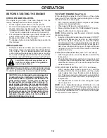
Страница 12: ...ion Never use engine or carburetor cleaner products in the fuel tank or permanent damage may occur TO START ENGINE See Fig 4 When starting the engine for the first time or if the engine has run out of fuel it will take extra cranking time to move fuel from the tank to the engine Sit on seat in operating position depress clutch brake pedal and set parking brake Place gear shift lever in neutral pos...

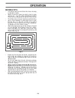
Страница 13: ...nces driveways etc After one or two rounds mow in the opposite direction making left hand turns until finished See Fig 8 If grass is extremely tall it should be mowed twice to reduce load and possible fire hazard from dried clip pings Make first cut relatively high the second to the desired height Do not mow grass when it is wet Wet grass will plug mower and leave undesirable clumps Allow grass to...

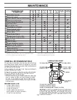
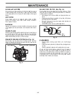
Страница 14: ... wear A new spark plug and clean air filter assure proper air fuel mixture and help your engine run better and last longer BEFORE EACH USE Check engine oil level Check brake operation Check tire pressure Check operator presence and ROS systems for proper operation Check for loose fasteners T R A C T 0 R 1 Change more often when operating under a heavy load or in high ambient temperatures 2 Service...

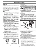
Страница 15: ...he ignition switch in the ROS ON position and the attachment clutch engaged any attempt by the operator to shift into reverse should NOT shut off the engine BLADE CARE Forbestresultsmowerbladesmustbekeptsharp Replace bent or damaged blades CAUTION Useonlyareplacementbladeap proved by the manufacturer of your tractor Using a blade not approved by the manu facturer of your tractor is hazardous could...

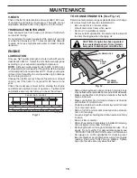
Страница 16: ... pressure water or steam to clean transaxle TO CHANGE ENGINE OIL See Fig 12 Determine temperature range expected before oil change All oil must meet API service classification C Be sure tractor is on level surface Oil will drain more freely when warm Catch oil in a suitable container Remove oil fill cap dipstick Be careful not to allow dirt to enter the engine when changing oil Slide oil drain ext...

Страница 17: ...sure there are no fuel line leaks and clamps are properly positioned Immediately wipe up any spilled gasoline Fig 15 FUEL FILTER CLAMP CLAMP AIR FILTER Your engine will not run properly using a dirty air filter Service air cleaner more often under dusty conditions See engine manual MUFFLER Inspect and replace corroded muffler and spark arrester if equipped as it could create a fire hazard and or d...

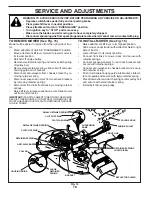
Страница 18: ... side of tractor Lower lift lever to its lowest position Connect front links to mower deck and secure with retainer springs Connect suspension arms to rear deck brackets and secure with retainer springs Connect anti swaybar to chassis bracket and secure with retainer spring Push clutch cable housing guide into bracket slide col lar onto guide and secure with large retainer spring Place flat washer...

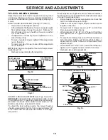
Страница 19: ...nt nut on that side To lower one side of mower loosen lift link adjustment nut on that side NOTE Each full turn of adjustment nut will change mower height about 1 8 Recheck measurements after adjusting BOTTOM EDGE OF MOWER TO GROUND Fig 16 Fig 17 A A GROUND LINE BOTTOM EDGE OF MOWER TO GROUND Checkadjustmentonrightsideoftractor Measuredistance D directly in front and behind the mandrel at bottom e...

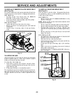
Страница 20: ...ve belt upwards from transaxle pulley by deflecting belt keep ers Remove belt from center span keeper and pull belt away from tractor BELT INSTALLATION Carefully work new belt down between transaxle belt keepers and onto the input pulley Slide belt into the center span keeper Pull belt toward front of tractor and roll around the top groove of engine pulley Install belt through stationary idler and...

Страница 21: ...short against tractor chassis ConnectoneendoftheBLACKcabletotheNEGATIVE terminal C of fully charged battery Connect the other end of the BLACK cable D to good chassis ground away from fuel tank and battery TO REMOVE CABLES REVERSE ORDER BLACK cable first from chassis and then from the fully charged battery RED cable last from both batteries Fig 24 WEAK OR DEAD BATTERY FULLY CHARGED BATTERY ADJUSTM...

Страница 22: ... is not adjustable If your engine does not operate properly due to suspected carburetor problems take your tractor to an authorized service center for repair and or adjustment TO REPLACE FUSE Replace with 20 amp automotive type plug in fuse The fuse holder is located behind the dash 02495 HOOD HEADLIGHT WIRE CONNECTOR REPLACING BATTERY See Fig 25 WARNING Do not short battery terminals by allowing ...

Страница 23: ...FUELSYSTEMPARTSSUCH AS CARBURETOR FUEL FILTER FUEL HOSE OR TANK DURING STORAGE ALSO EXPERIENCE INDICATES THAT ALCOHOL BLENDED FUELS CALLED GASOHOL OR USING ETHANOLORMETHANOL CANATTRACTMOISTUREWHICH LEADSTOSEPARATIONANDFORMATIONOFACIDSDURING STORAGE ACIDIC GAS CAN DAMAGE THE FUEL SYSTEM OF AN ENGINE WHILE IN STORAGE Empty the fuel tank by starting the engine and let it run until the fuel lines and ...

Страница 24: ...own fuse 4 Replace fuse 5 Corroded battery terminals 5 Clean battery terminals 6 Loose or damaged wiring 6 Check all wiring 7 Faulty ignition switch 7 Check replace ignition switch 8 Faulty solenoid or starter 8 Check replace solenoid or starter 9 Faulty operator presence switch es 9 Contact an authorized service center department Engine clicks but will not start 1 Weak or dead battery 1 Recharge ...

Страница 25: ... Replace blade Tighten blade bolt 7 Buildup of grass leaves and trash under mower 7 Clean underside of mower housing 8 Mower drive belt worn 8 Replace mower drive belt 9 Blades improperly installed 9 Reinstall blades sharp edge down 10 Improper blades used 10 Replace with blades listed in parts manual 11 Cloggedmowerdeckventholesfrombuildup of grass leaves and trash around mandrels 11 Clean around...

Страница 26: ...26 SERVICE NOTES ...
Страница 27: ... never across the face Do not mow slopes greater than 15 degrees Make turns gradually to prevent tipping or loss of control Exercise extreme caution when changing direction on slopes 1 Fold this page along dotted line indicated above 2 Hold page before you so that its left edge is vertically parallel to a tree trunk or other upright structure 3 Sight across the fold in the direction of hill slope ...

Страница 28: ...sed for rental or commercial purposes is limited to 90 days from the date of origi nal purchase 5 This Warranty applies only to products which have been properly assembled adjusted operated and maintained in ac cordance with the instructions furnished This Warranty does not apply to any product which has been subjected to altera tion misuse abuse improper assembly or installation delivery damage o...

Отзывы: