Publication No. 5105703
14 Installation
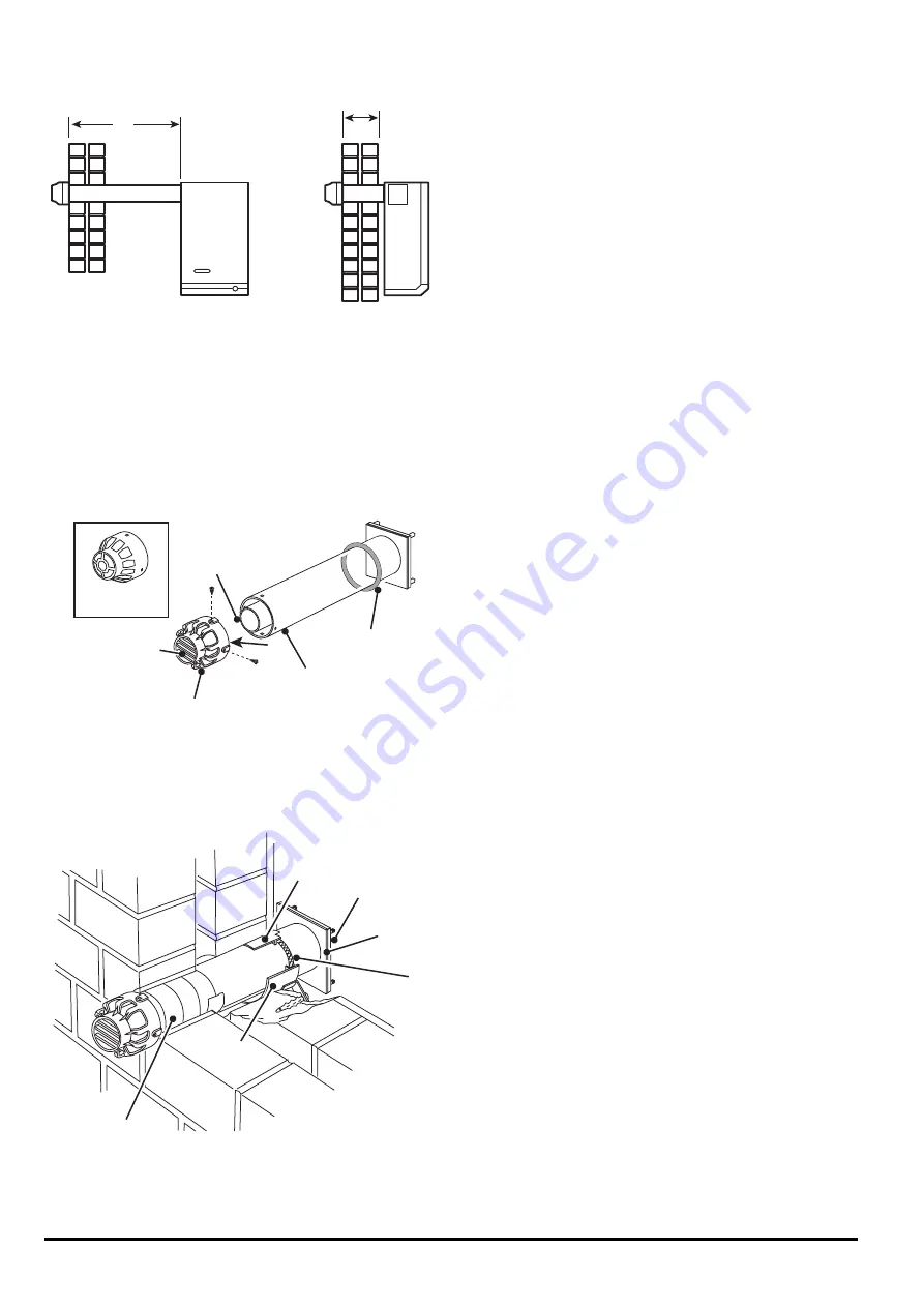
Fig. 13
2.4.
The Flue
Side Flue
1. Measure from outside face of wall to the
side of boiler casing reference line (dimension
'x').
2. Take air/flue duct assembly and measuring
from the flanged end mark and cut the outer
duct and inner flue duct to dimension 'x' plus
20 mm.
Ensure that both ducts are cut squarely.
Note: Cutting length remains the same for
minimum or maximum clearance at the rear of
the boiler.
Rear Flue
1. Measure wall thickness (dimension 'y').
2. Take air/flue duct assembly and measuring
from the flanged end mark and cut the outer
duct and inner flue duct to dimension 'y' plus
48 mm, or dimension 'y' plus 58 mm if boiler
mounting plate has been inverted.
Ensure that both ducts are cut squarely.
2.5.
Air/Flue Duct Assembly
Note: During assembly the seam in the air duct
should be so arranged that when installed, the
seam in the duct will be uppermost.
1. Slide rope sealing ring on to air duct.
2. Engage the terminal on to the ends of the
inner flue duct and press fully home.
Note: On 60 & 80 models there is a silicone seal
on the inner edge of the terminal. This is to
prevent recirculation of flue products.
3. Engage four screws from accessory pack C
into the pre-drilled holes in the terminal and
screw fully home.
These screws are self tapping on 60 & 80
models. These will pierce the air duct and
secure the terminal to it.
On the 40 and 50 models it is necessary to
drill four pilot holes in the air duct.
4. Protect the duct where it is likely to come
into contact with mortar by using adhesive
tape provided in accessory pack E.
PRF0014A
'Y'
'X'
PRF0015B
Rope Sealing
Ring
Air Duct
Terminal
40 to 50
Inner
Flue
Duct
Discharge
Vanes
PRF0016A
Sealing
Gasket
Air Duct
Flange
Rope
Sealing
Ring
Tab
Tab
Tape
Fig. 11
Fig. 12


