Page 3
V. HARDWARE INSTALLATION
A.
2
nd
LCD Monitor
Please refer to following installation and join the 2
nd
LCD monitor to XP-
2000 series step by step.
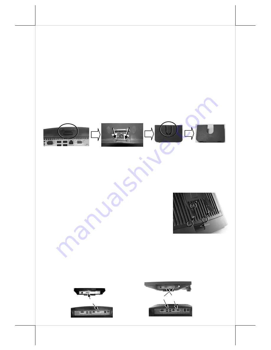
1. Cable Exit Cover
Please release the cable exit cover as following steps:
A: Please find the back of cable cover which just near the I/O plate.
B: Please use the Fingertip to release compression lock.
C: after the cable cover released, please cut the circle part which show in the
picture C.
After finish this step, the cable cover can be use when the rear mount upgrade
kits fixed.
2. Mount the bracket to XP-2000 series’ back cover
Please aim to the three screws holes of bracket to the
terminal’s back cover’s screws holes as show on the
picture. Then fasten the screws which come with
LM-2208/LM-2212/TM-2212. After fix the LM-
2208/LM-2212/TM-2212 to the XP-2000 series,
please use the cable exit to pass through the VGA
cable to the terminal’s I/O plate.
Next, please use the VGA Cable to connect to the LM-2208/LM-2212/TM-
2212 and XP-2000 series’ VGA ports as well as use the attached USB cable to
connect TM-2212 and XP-2000 series’ USB Port. After these steps, the
installation process of LM-2208/LM-2212/TM-2212 is finished. For power
supply of VGA ports in XP-2000 series, please contact to local dealer of
authorized technicians.
B
A
C
VGA
LM-2208
VGA
TM-2212
USB


