5
4
POSI LOCK®
100-TON & 200-TON
Hydraulic Puller Systems
Pushers | Jaw Tips
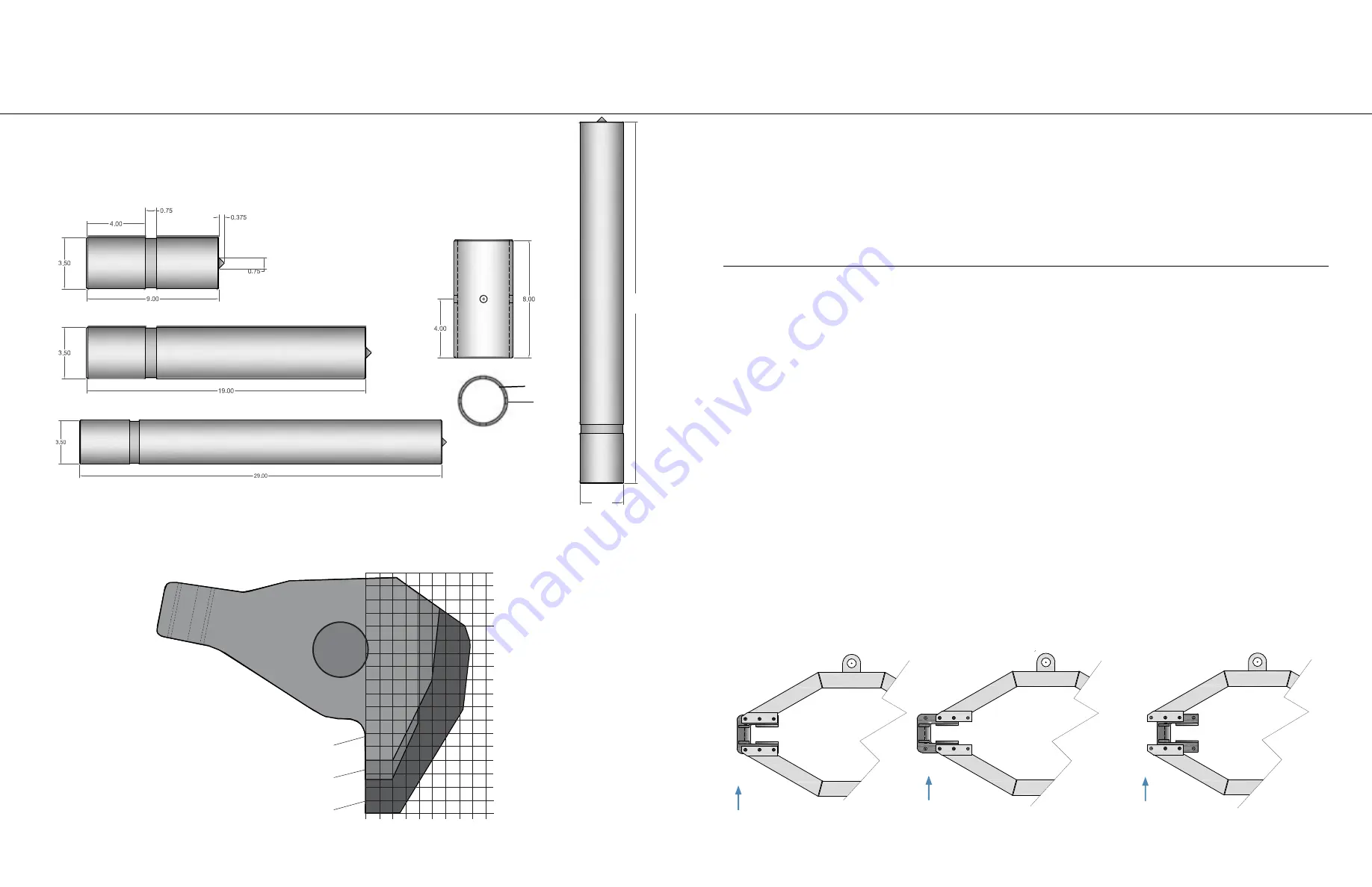
PUSHERS:
Included with the 100-Ton pullers are THREE pushers and a coupler. String 2 pushers together to increase the reach
of the ram. Using a variety of combinations may be necessary to complete the pull of a deeply set gear or bearing.
Included with the 200-Ton puller are FOUR pushers. The diameters are 4 inches. The 200-T does not include a
coupler.
Coupler
*Not included with the
200-Ton.
JAW TIPS:
3 jaw tip sizes are available for 100 and 200 Ton puller models.
•
HT-1180: standard with all models.
•
HT-1180A: optional, for operations with limited space constraints.
•
HT-1180S: optional, for operations with limited space constraints.
39.00
*Included with
200-Ton only.
4
HT-1180S
HT-1180A
HT-1180*
0.0
0.5
1.0
1.5
2.0
2.5
3.0 3.5 4.0
4.5
0.0 in.
0.5
1.0
1.5
2.0
2.5
3.0
3.5
4.0
4.5
5.0
5.5
6.0
6.5
7.0
7.5
8.0
8.5
9.0
*Tip widths are 3 inches thick.
ADJUSTMENTS:
RAISING THE PULLER:
1. Place cylinder control valve lever in “Hoist Oil Supply” position.
2. Raise puller by placing remote jog switch in “On” position and opening the puller hoist vertical control valve.
3. Release remote jog switch. Close vertical control valve after reaching desired height.
LOWERING THE PULLER:
1. Place cylinder control valve lever in “Hoist Lower” position.
2. Lower puller by turning puller hoist vertical control valve counterclockwise.
3. Close vertical control valve after reaching desired height.
NOTE:
HOIST TRAVEL SPEED:
The restrictor valve, located at the top of the hoist cylinder, is used to control the rate of puller descent. This valve should be set at
the desired rate and locked in place using the nut on the valve shaft.
An appropriate starting point is one full turn from the closed position. This valve is a one-way restrictor only and does not affect
the rate at which the puller is raised.
POSI LOCK®
100-TON & 200-TON
Hydraulic Puller Systems
Assembly | Adjustments
ASSEMBLY:
1. Ensure that shipping crate firmly rests on level ground in upright position.
2. Open small side panel and confirm that puller is resting firmly in upright position in the create.
3. Remove remainder of plywood.
4. Inspect puller for any damage that may have been caused by shipping.
5.
Save bolts
that were used to brace the cart. These will be used for securing the included cart wheels to the cart.
6. Inspect hoses for proper ratings. Connect the 10,000 psi hose to the port marked “
10,000 psi only”
on the puller and the
pressurized port on the pump. Connect hose with the lower pressure rating to the return port on puller and pump.
7. Fill reservoir of pump with pump manufacturer specified oil. See pump or cylinder manual for details.
Jaw guide moved 1 bolt hole
OUT
to increase spread.
CHANGING THE JAW SPREAD:
If opening/closing the jaws using the standard cage setting does not provide enough spread or does not provide enough closure,
use the following adjustments to achieve the maximum and minimum spreads.
1. Support the jaws.
2. Remove 6 cap screws, lock washers and nuts on 1 jaw guide at a time.
3. Slide jaw guide inward/outward on cage 1 bolt hole.
4. Replace 4 cap screws, lock washer, and nuts and tighten appropriately.
5. Reverse this process to return to standard jaw spread.
Jaw guide moved 1 bolt hole
IN
to decrease spread.
Default jaw guide position
when puller is shipped.
3.52
4
HT-1164
HT-1163
HT-1162


