


72
Specification
AnyShop Eco
CPU
Intel Atom processor D525 (1M Cache, 1.8 GHz, Dual Core for Pineview D)
Chipset
Intel ICH8M
Storage
SATA HDD 2.5inch (Default 320GB), SSD is available by option
Memory
DDR3-800MHz SODIMM 2GB (MAX. 4GB)
VGA
Integrated Intel Gen3.5+GFX Render Core 400MHz (Pineview-D)
Display
15" TFT-LCD 300 cd/
㎡
(1024 x 768 resolution) 5-wired Resistive Touch Screen
Internal I/O
USB
3 Ports (reserved for touch controller, SCR EMV card, MSR controller)
RS-232
COM 4 reserved for CDP
COM 5 & 6 with 9pin header
VGA
Reserved for 2nd display
Extension
Mini PCIe
LVDS
24bit LVDS
External I/O
USB
Rear 2, Side 2
PS/2
Mouse 1 / Keyboard 1
RS-232
COM 1 ~ 3 with +5/12V power output on 9pin
LAN
Realtek RTL 8111E Gigabit LAN
VGA
Reserved for 2nd display (Shared with internal 15pin header)
Audio
ALC 892 GR / Rear panel out(jack): Line-out, Mic-in, Line-in
Options
MSR
Comply with ISO 7811, Support 1 & 2 & 3 track
SCR
EMV level 1
Dallas
Dallas I-button reader
Customer display
VFD type (20 x 2)
2nd LCD
10.1" LCD or 12.1" LCD (1024 x 768 resolution)
WiFi
Mini PCIe for wireless LAN
Operating Temperature
0
℃
~ 40
℃
at 10% ~ 80% humidity
Storage Temperature
-20
℃
~ 60
℃
at 10% ~ 80% humidity
Qualification
CE, FCC, KC
Power
12V / 5A Adaptor
OS Support
Windows XP/XPE/7, WEPOS, POS Ready 2009/7
Dimension (W x H x D)
385 x 395 x 265(mm)
* Product specifications may differ according to location and may be changed without prior notice.
*MSR is supported USB interface only
Содержание AnyShop Eco
Страница 1: ...Point of sale system AnyShop Eco User s manual PBUM 017E Rev004 130530...
Страница 16: ...16 Rear view 1 USB port 2 I O port 3 Customer display CDP optional 4 HDD 5 Stand 3 4 1 1 2 5...
Страница 17: ...17 Standard I O port 1 2...
Страница 26: ...26 11 Setting up Printer Connection Connect printer cable to either Serial or USB port as required...
Страница 34: ...34 3 Side USB Board Side USB Board Connector Description A To Motherboard USB A...
Страница 35: ...35 4 Power Switch Board Power Switch Board Connector Description A Power switch A...
Страница 37: ...37 6 Drawer Port Board Drawer Port Board Connector Description A From Drawer Kicker B Cash Drawer port A B...
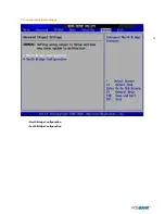
Страница 58: ...58 3 13Advanced Chipset Settings North Bridge Configuration South Bridge Configuration...
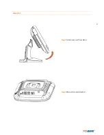
Страница 67: ...67 Main Unit Step 3 Detach main unit from stand Step 4 Main unit is now detached...


