Copyright 2016 © Portable Rotation, Inc.
Page 7
-
Attach the 18 inch arms in a similar manner with slight pressure on the arms
towards the Rotor Housing
-
DO NOT Over tighten the set screws.
Installation
Installing the Rotor system for portable Use is not difficult.
Before starting the installation VERIFY that the site is in a safe
location to erect an antenna system of the size you are using.
Make sure there are no overhead power wires nearby
. Also
make sure there are no buildings, structures, or trees that the
turning antenna could strike causing potential damage.
Eye protection should be worn when installing the antennas. Large antennas
with crossing elements can be an eye danger especially when installing them
at eye level.
Even though this is a low power 12 volt device, the high gear ratio of the mechanism
could cause damage if rotating your antenna into a fixed objects.
Use the provided Velcro strips to attach the feed line Coax and Rotor Cable to the
tripod or mast in a few locations to keep the cables from dragging on the ground or
moving in the wind. It is recommended to attach the cables to the mast in the
opposite general direction of the satellite to be tracked, reducing the amount of cable
wrap for your feed line. Remember to include a service loop in the Coax to allow for
the rotation.
There are multiple connections on the Azimuth or lower rotor unit. Each connector
has a different pin count so it is not possible to make the wrong connection. Connect
the Elevation or Top Rotor unit to the Azimuth unit with the 6 conductor cable. Once
the antenna(s)/tripod/mast is erected, connect the 4 conductor rotor cable to the
Rotor Controller and connect 12 Volts to the Hand Controller using the provided
power cable.
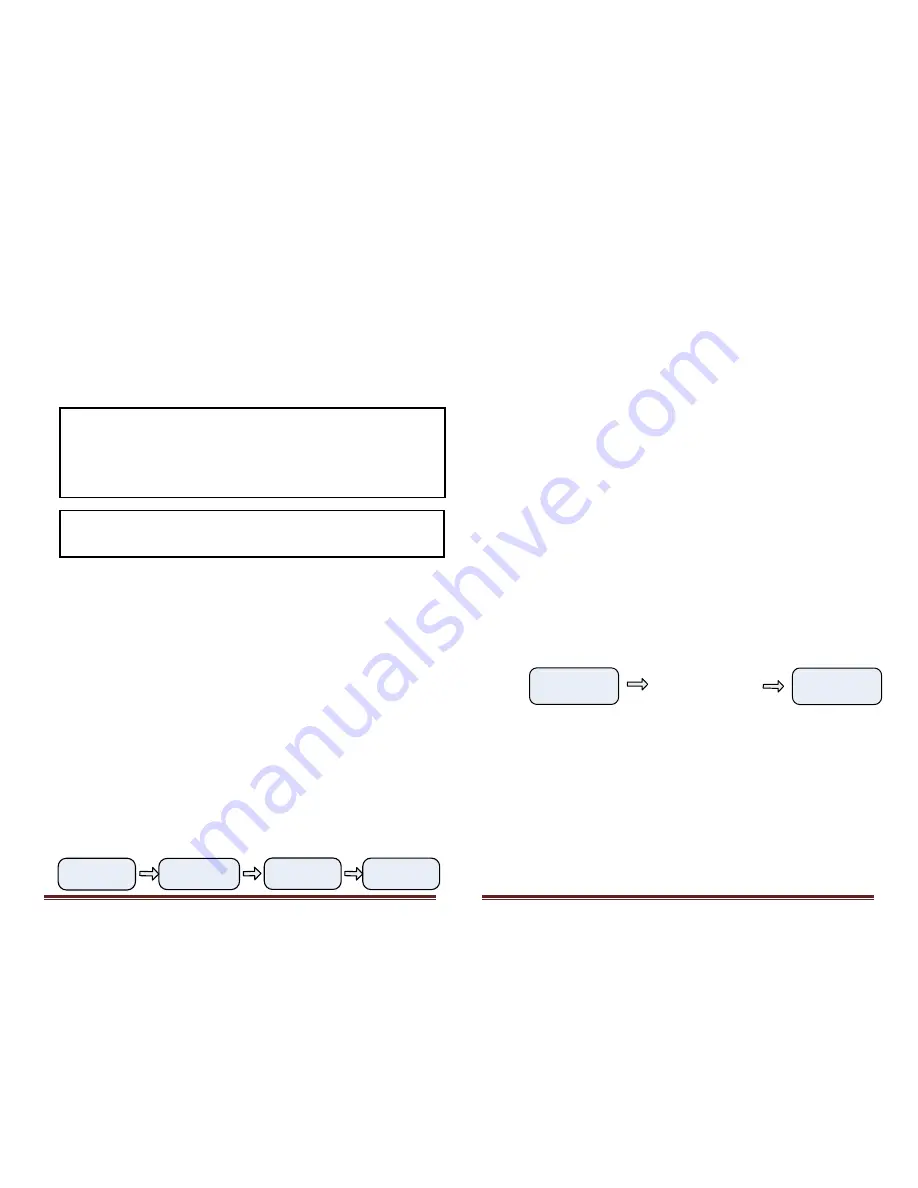
Once the controller is turned on, the following start up messages are displayed with
the final display showing the user configurable 8 character top line and the last known
antenna heading:
Model
12PRSAT
InitComs
to Rotor
Portable
Rotation
PTBL RTN
A000E000
Copyright 2016 © Portable Rotation, Inc.
Page 8
New Deployment Configuration
After erecting your portable antenna system (including Tripod, Rotor Head, Antennas,
Feed Line and Rotor Cable) you will need to calibrate the antenna Azimuth and
Elevation, and make any changes to the 8 characters of user programmable message.
With the ‘Any-Direction’ Calibration feature of this controller, you can erect the
antenna system and not worry about the antenna heading at that time. This saves
time and the effort of trying to align the antenna to its proper azimuth and elevation
by adjusting U-Bolts and clamps.
Using the provided compass, smart phone application or other device, make note of
the current heading of the antenna. Again, you do not need to have the physical
antenna heading set to North when first erecting the antenna system; you will set the
initial heading of the antenna into the controller during the power on initialization
process. Make sure to position your feed lines such that you minimize antenna mast
wrapping.
Set the Initial Heading and Azimuth
A compass points to Magnetic North. Due to the varying magnetic fields of the Earth,
‘Magnetic’ North and ‘True’ North are not always the same. When tracking satellites,
true North is used. You will need to adjust your Heading entry based on both the
Magnetic North reading and the Declination for you area. There is a lot of information
on the web that can be referenced to further understand Magnetic Declination.
Next go to the controller and turn the system on, when the Initial “Portable Rotation”
messages is displayed holding down the Mode button [Middle Button]. Continue
holding the button until the “Select / Az Bt El” message is displayed. Release the
button.
PTNL RTN
A123E045
Select
Az Bt El
Selecting Bt for both
you will now enter
both initial headings.
Select Az for Azimuth, Bt
for Both or El for Elevation
Initial Az and El values now set
to Azimuth=123 degrees and
Elevation of 45 degrees
You can now choose to set the Initial Azimuth, Elevation or both. Press the CCW
button to select Azimuth, MORDE button to set both or the CW Button to set the
initial Elevation value.


