background image


ATTENTION 

This module contains ESD components! (ESD = Electrostatic Sensitive Device).   

An  electrostatic  discharge  is  an  electrical  current  pulse,  which  can  flow  also  through  an  electrically 

insulated material, when triggered by large voltage difference. 


To ensure the reliability of ESD components, it is necessary to consider their most important handling rules:   

Electrostatic sensitive components can be processed only on electrostatic protected area (EPA)!   

  Pay attention permanently to potential equalization (equipotential bonding)!   

  Use wrist straps, approved footwear for personnel grounding!   

  Avoid electrostatically chargeable materials such as normal PE, PVC, polystyrene!   

  Avoid electrostatic fields >100 V/cm !   

  Use only labeled and defined packing and transportation materials!   


Damage caused by faulty connections and / or improper handling are excluded from any liability.


Waste disposal 


Electronic  equipment  does  not  belong  in  household  waste,  but  must  be  disposed  of  properly  in  accordance  with 

Directive  2002/96/EC  of  the  European  Parliament  and  of  the  Council  of  27  January  2003  on  waste  electrical  and 

electronic equipment (WEEE). 

Please return this device to the designated public collection points at the end of its use for disposal. 


WEEE-Reg.-Nr. DE 51035844 


GENERAL INFORMATION ON THE OPERATING INSTRUCTIONS 


All parameter data are exemplary only.   


Technically realizable parameters are freely selectable. 


Menu views can vary slightly depending on the software version; the operability does not change as a result. 

   The images in this manual are for illustration purposes only.


Содержание HDI 32 C

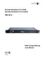
Страница 1: ...1 Encoder Modulator IP in QAM Encoder Modulator IP into QAM HDI 32 C Bedienungsanleitung User Manual 0902003...

Страница 2: ...2 Montage und Sicherheitshinweise...

Страница 3: ...3 Mounting and safety instructions...

Страница 4: ...statische Felder 100 V cm vermeiden Nur gekennzeichnete und definierte Verpackungs und Transportmaterialien einsetzen Sch den durch fehlerhaften Anschluss und oder unsachgem e Handhabung sind von jegl...

Страница 5: ...ic fields 100 V cm Use only labeled and defined packing and transportation materials Damage caused by faulty connections and or improper handling are excluded from any liability Waste disposal Electro...

Страница 6: ...er 2 Housing and connections 2 1 Darstellung der Frontseite Front view 2 2 Darstellung der R ckseite Rear view Kapitel 3 Installationsanleitung Chapter 3 Installation guide 3 1 Lieferumfang Scope of d...

Страница 7: ...system 1 2 Hauptmerkmale Key features 2x GE Eingang RJ45 Schnittstelle 2x GE input RJ45 interface Unterst tzt bis zu 1024 Kan le TS ber UDP RTP Unicast und Multicast IGMP v2 v3 Supports up to 1024 cha...

Страница 8: ...8 1 3 Blockdarstellung Principle chart 1 4 Darstellung der Tr gereinstellung Carrier setting illustration 384 M Startfrequenz Start frequency Endfrequenz End frequency...

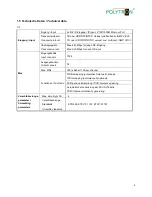
Страница 9: ...Eingang Max 840 Mbps for each GE input Mux Eingangskan le Input channels 1024 Ausgangskan le Output cannels 32 Max PIDs 180 je Kanal 180 per channel Funktionen Functions PID Remapping automatisch man...

Страница 10: ...HF Bereich RF range 50 960 MHz 1 kHz Schritte Stepping Ausgangspegel Output level 20 10 dBm 87 117 db V 0 1 dB Schritte Stepping MER 40 dB ACLR 60 dBc TS Ausgang TS output 32 IP Ausgabe ber UDP RTP R...

Страница 11: ...etzkontroll LED Mains control LED 2 2 Darstellung der R ckseite Rear view 3 HF Ausgang RF output port 4 Reset IP Zur cksetzen der Webmaster IP Adresse Wiederherstellen der Standard IP Adresse Reset we...

Страница 12: ...n Den Einsatzort entsprechend vorbereiten Preparing relevant environment for installation Den Modulator installieren Install the modulator Die Signalkabel anschlie en Connecting signal cables Den NMS...

Страница 13: ...rn 0 255 oder bereits verwendete IP Adressen Diese Einstellung kann unter Netzwerkverbindungen LAN Verbindung vorgenommen werden Connect the PC notebook to the NMS socket using a standard network cabl...

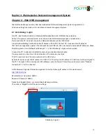
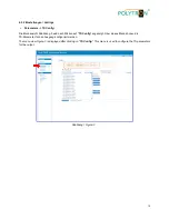
Страница 14: ...e appropriate menu item to check information or set the parameters 4 2 Betrieb Operation 4 2 1 Zusammenfassung Summary Nach Best tigung der Anmeldedaten wird die folgende Men ansicht als Abbildung 2 a...

Страница 15: ...ildung 3 wird nach Klicken auf TS Config angezeigt ber dieses Men k nnen die TS Parameter f r den Ausgang konfiguriert werden The menu view Figure 3 is displayed after clicking on TS Config This menu...

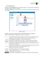
Страница 16: ...wird die Auswahlliste der TS Ausgangskan le 1 32 angezeigt Wie in Abbildung 4 ersichtlich k nnen so die TS Ausgangskan le ausgew hlt werden After clicking on the triangle symbol next to Output TS x t...

Страница 17: ...ren deaktivieren Enable disable PID remapping Aktualisierung der Programminformation am Eingang To refresh the input program information Aktualisierung der Programminformation am Ausgang To refresh th...

Страница 18: ...H1_GE1 it triggers a dialog box Figure 6 where users can input new information Abbildung Figure 6 Nachdem die Einstellungen get tigt sind diese mit Klick auf Apply bernehmen After the settings have be...

Страница 19: ...che keinem Programm zugeordnet werden k nnen z B EPG NIT Tabellen usw Diese sollen aber am Ausgang ohne Ver nderungen ausgegeben werden After clicking on PID Bypass the input window is displayed in wh...

Страница 20: ...to be encrypted Abbildung Figure 10 Auswahl des Verschl sselungskanals Scramble channel select Auswahl des CA Kanals CA channel select Anzeige der aktuell ausgegebenen Programme Die ausgew hlten Prog...

Страница 21: ...n the left click on Modulator to open a dialog box Figure 11 where the RF output settings can be made Abbildung Figure 11 Hier klicken um die HF Ausgangs parameter f r alle QAM Kan le einzustellen Cli...

Страница 22: ...32 C modulator supports TS output in IP format 32 MPTS via the data interface In the selection bar on the left click on IP Stream to open a dialog box Figure 12 where the IP output settings can be ma...

Страница 23: ...tzwerk wird die Eingabemaske Abbildung 13 angezeigt in der man die Netzwerkparameter einstellen kann After clicking on Network the input mask Figure 13 is displayed in which it is possible to enter th...

Страница 24: ...alogfeld Abbildung 14 ge ffnet ber das die Einstellungen betreffend Login und Passwortschutz vorgenommen werden k nnen In the selection bar on the left click on Password to open a dialog box Figure 14...

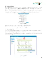
Страница 25: ...bschlie ende Ger tekonfiguration Save Restore Factory Set Backup Load vorgenommen werden kann Click on Configuration in the selection bar on the left hand side and a dialog box Figure 15 will open whe...

Страница 26: ...owse den entsprechende Order mit dem Firmware Update suchen und die Datei ausw hlen Danach auf Upgrade klicken Click on Firmware in the selection bar on the left hand side and a dialog box Figure 16 w...

Страница 27: ...icken so wird ein Dialogfeld Abbildung 17 ge ffnet ber das die Log Daten Kernel und System Log berpr ft werden k nnen Click on Log in the selection bar on the left hand side and a dialog box Figure 17...

Страница 28: ...hme H Q Order department 49 0 70 81 1702 0 Technische Hotline Technical hotline 49 0 70 81 1702 0 Telefax 49 0 70 81 1702 50 Internet http www polytron de eMail info polytron de Technische nderungen v...

Отзывы: