background image


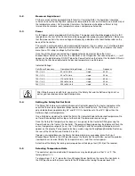
To change from °F to °C, place the Circuit Breaker/Power Switch in the OFF position and then press 

and hold the P3 Button while turning the power back ON. 

NOTE: When the temperature display units are changed, the Software High Limit value and all 

temperature presets revert to the factory-default values. If a calibration value has been entered, the 

value will be retained.  

5.6 

Setting the Software High Limit 

This feature provides additional safety and protection by allowing a selectable upper temperature 

limit set point. To avoid an unwanted shutdown during regular operation, the high limit value should 

be set at least 5°C higher than the selected control temperature  

To set the Software High Limit temperature set point, press the P2 and P3 keys simultaneously and 
repeat until (Hxxx) appears on the display. This is the current Software High Limit value. It is factory 

set at 152°C. 

To change the displayed value, press and turn the Select/Set Knob until the desired Software High 

Limit set point value is displayed. A clockwise rotation increases the value; a counterclockwise 

rotation decreases the value. Press the Select/Set Knob a second time to accept the new value and 

return to normal operation. 

If the Software High Limit value meets or exceeds the control temperature set point, (E-H1) will flash 

on the display. If this occurs, enter a higher value for the Software High Limit or reduce the control 

temperature set point.  
If the actual bath temperature reaches the Software High Limit setpoint, (FLt1) will flash on the 

display. Should this occur, the Controller will automatically remove power from the heater and, in 

Refrigerating/Heating units, the compressor as well. The pump will continue to operate.  
Once the problem is corrected (bath temperature reduced or Software High Limit value increased), 

press the Power button to clear the message. 

5.7 

Setting the Set Point Temperature 

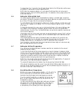
Press and release the Select/Set Knob. The decimal point flashes to indicate that the set point 

temperature can be changed.   

Turn the Select/Set Knob until the desired temperature set point is displayed. A clockwise rotation 

increases the setting; a counterclockwise rotation decreases the setting. Press the Select/Set Knob 

a second time to accept the displayed value. The decimal point stops flashing and the display will 

indicate the actual bath temperature. Allow sufficient time for the bath to stabilize at the desired 
temperature before making any adjustments to set point temperature. 

NOTE: The unit will automatically accept the displayed set point after approximately 10 seconds of 

inactivity, even if the Select/Set Knob was not pressed.   

The set point temperature may be checked at any time by pressing the Select/Set Knob.  

If the set point temperature cannot be raised, it is possible that the Software High Limit value is set 

lower than the desired control temperature set point. Reset the Software High Limit value to 5°C or 

more above the desired set point temperature.   

5.8 

User-Defined Preset Temperatures 

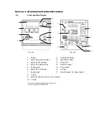
With the unit on, press the desired Preset Button — P1, P2, or P3. The 

LED associated with the selected Preset Button will begin to flash. 

Rotate the Select/Set Knob to the desired temperature set point. 
Press the selected Preset Button a second time to enter the new set 

point. The new set point temperature will not be saved unless the 

Preset Button is pressed. 
The LED associated with Preset Button lights continuously whenever 

that preset value is controlling bath temperature. If more than one 

Preset Button is set at a given temperature set point, the LED 

associated with all Preset Buttons with that set point will light. 

Содержание Standard Controller

Страница 1: ...Operators Manual Standard Controller Models Pages 1 22 Manuel de l utilisateur Mod les du Contr leur Standard Pages 21 37 Bedienungsanleitung Ger te mit Standardregelung Seiten 38 54 110 227 1 8 08...

Страница 2: ...D 1150S 1157P 1196D 1190S 1197P 1186D 1180S 1187P 1136D 1130S 1137P 1136 1D 1130 1S 1137 1P 1136 2D 1130 2S 1137 2P 12110 00 12110 05 12112 01 12112 06 12112 11 12112 16 12112 12 12112 26 12100 10 121...

Страница 3: ...rces prudently and rationally Specific treatment of WEEE is indispensable in order to avoid the dispersion of pollutants into the recycled material or waste stream Such treatment is the most effective...

Страница 4: ...130S 1137P 1136 1D 1130 1S 1137 1P 1136 2D 1130 2S 1137 2P 12110 00 12110 05 12112 01 12112 06 12112 11 12112 16 12112 12 12112 26 12100 10 12100 15 12100 20 12100 25 12108 00 12108 05 12108 20 12108...

Страница 5: ...0S 1137P 1136 1D 1130 1S 1137 1P 1136 2D 1130 2S 1137 2P 12110 00 12110 05 12112 01 12112 06 12112 11 12112 16 12112 12 12112 26 12100 10 12100 15 12100 20 12100 25 12108 00 12108 05 12108 20 12108 25...

Страница 6: ...tting the Safety Set Set Point 5 5 Selecting Temperature Units 5 6 Setting the Software High Limit 5 7 Setting the Set point Temperature 5 8 User Defined Preset Temperatures 5 9 Local Lockout Feature...

Страница 7: ...is warranty is limited to the repair or replacement of a defective product and shall not in any event be liable for any incidental or consequential damages of any kind resulting from use or possession...

Страница 8: ...ration at temperatures below 40 C However refrigeration should not be used when the fluid temperature is above 55 C Refrigeration should not be turned on when the ambient air temperature is above 32 C...

Страница 9: ...h the unit are intended for applications from 40 C to 93 C For applications above 93 C brass stainless steel or Teflon fittings are recommended inch NPT to M16 stainless steel male adapter fittings ar...

Страница 10: ...for a wide variety of applications Model Type Temperature Range Reservoir Capacity Amps 120V 60Hz Amps 240V 50Hz Heat Only Immersion Circulator Ambient 5 C to 150 C N A 11A 7 5A 3 3 Circulator Pump Th...

Страница 11: ...ing over the rotating pump outlet nozzle and fasten it in place with a hose clamp Connect the other end of the tubing to the inlet of the external apparatus Be sure to run tubing from the outlet of th...

Страница 12: ...eset Button 13 Pump Inlet 2 4 Safety Set Indicator Knob 14 Reservoir Purge 2 5 Cooling Light 1 15 Pump Outlet 2 6 Power ON OFF Button 16 AC Input 7 Heating Light 17 Circuit Breaker AC Power Switch 8 F...

Страница 13: ...the Circulator on a level surface free from drafts and out of direct sunlight Do not place it where there are corrosive fumes excessive moisture high room temperatures or excessive dust is present Re...

Страница 14: ...After filling the reservoir with fluid you must set the Safety Set and the Software High Limit as well as your desired control set point temperature 5 4 Setting the Safety Set Set Point The Safety Set...

Страница 15: ...the problem is corrected bath temperature reduced or Software High Limit value increased press the Power button to clear the message 5 7 Setting the Set Point Temperature Press and release the Select...

Страница 16: ...ons a set point 15 C above room temperature is recommended Cool Command Refrigeration Refrigerating Heating Circulators with 13 and 28 liter reservoirs feature the advanced Cool Command modulating ref...

Страница 17: ...FLt 5 Probe failure Error Service required FLt 6 i2c error Communication failure to modulation board Error Service required Appears only on Refrigerating Heating Circulators Section 6 Calibration and...

Страница 18: ...ing capacity the condenser the front and back air vents and reusable filter should be kept free of dust and dirt They should be checked on a scheduled basis and cleaned as required The reusable filter...

Страница 19: ...o stabilize when changes in heat load or set point are made 7 6 No Cooling or Insufficient Cooling Check that the Cooling switch is ON If the cooling light is not lit check the control temperature set...

Страница 20: ...RMAL EXTREME 25 C RANGE RANGE Distilled Water 1 00 10 90 C 2 100 C Ethylene Glycol 30 Water 70 90 0 95 C 15 107 C Ethylene Glycol 50 Water 50 82 20 100 C 30 100 C Dynalene HC 50 76 50 60 C 62 60 C DC2...

Страница 21: ...s high temperature extreme 1 Heat loss from vapor adversely affects temperature stability 2 To prevent the accumulation of vapors inside the room the reservoir may need to be placed in a fume hood 3...

Страница 22: ...Refrigerating Heating and Heating Only models 120V 525 525 Pump Motor Refrigerating Heating and Heating Only models 240V 525 526 Pump Motor Immersion Circulators 120V 525 527 Pump Motor Immersion Cir...

Отзывы: