background image

10

SETUP INSTRUCTIONS

Before assembly, take a few minutes to identify and become familiar with all the parts.

Preliminary Steps:

1. READ ALL INSTRUCTIONS CAREFULLY and get a thorough understanding of what is required to assemble this product.

2. Set up your pool and filter pump following the pool/filter owner’s manual instructions.

3. Place the Salt Water System in line after your filter pump as indicated in 

Fig. 1

.

    If the pool is filled with water, use the Service Plugs provided with Polygroup

®

 aboveground pool filter pumps to block the pool’s inlet and outlet before installing this 

    Salt Water System.

IMPORTANT:

 NEVER use this Salt Water System without a filter pump.

This Salt Water System requires a SEPARATE FILTER PUMP with a flow rate between 600-4000 gph (2271-15140 lph) to drive the water and function properly. The 

Salt Water System MUST BE INSTALLED AS THE LAST PIECE OF POOL EQUIPMENT IN THE WATER RETURN LINE TO THE POOL as indicated in 

Fig. 1

.

FIG.1

FILTER

PUMP

SWIMMING POOL

Connecting the system to pump and pool

27

24

16

31

26

Outlet

Inlet

Cartridge Filter Pump

Sand Filter Pump

Skimmer Filter Pump

Pump outlet locations of Polygroup

®


filter pumps (for connecting to this 

Salt Water System)

System Installation

1. Connect to the filter pump’s OUTLET:

    a. Remove the return hose from the pump outlet.

    b. At the Cell Inlet 

u

, check and make sure the Strainer Grid 

y

 and the Connecting Tube 

r

 are in place, firmly tightened by the Metal Hose Clamp 

;

. Then 

        install the Connecting Tube into the pump outlet.

    c. If needed, use the Universal Adaptor 

l

 for a secure connection to a filter pump hose.

    d. Remove the Service Plug that blocked the pool’s outlet (if any).

2. Connect to the pool’s INLET:

    a. Attach the Cell Outlet 

g

 to the Hose 

x

, firmly tightened by the Plastic Hose Clamp 

t

.

    b. Remove the Service Plug that blocked the pool's inlet (if any), and secure the Hose to the pool inlet.

3. Check the Cell Lock Nut 

j

 to make sure that there's no water leakage.

Содержание SUMMER WAVES P5E000400

Страница 1: ...troubleshooting issues please visit support polygroupstore com Customer Service 1 888 919 0070 You may be asked to return all or part of the product for inspection and or repair Do not return any prod...

Страница 2: ...ly to the repair or replacement of the product to be decided in Polygroup s sole discretion Consequential damages including claims for loss of water pool chemicals damage or labor are not covered unde...

Страница 3: ...icating the possibility of an electric shock Do not use this pump Disconnect the pump and have the problem corrected by a qualified service representative before using Safety Care for Children 1 Child...

Страница 4: ...l be installed per manufacturer s instructions to provide proper mounting and support to prevent damage from misalignment settlement and vibration and to minimize the potential for the accumulation of...

Страница 5: ...r loose bolts that could make the deck unsafe 14 Please contact pool site dealer or manufacturer for additional safety signs if deemed necessary 15 For pool service select a certified pool professiona...

Страница 6: ...dential Swimming Pools Spas and Hot Tubs Installer Responsibilities All of these components shall be positioned so as to prevent their being used as a means of access to the pool by young children See...

Страница 7: ...sanitizing agents already commonly used in swimming pools As such a saltwater pool is not actually chlorine free it simply utilizes a chlorine generator instead of direct addition of chlorine AC 120V...

Страница 8: ...icator Power Mode Button Main Body Foot Stand AC Power Cord Cell Connection Cord Connecting Tube for filter skimmer Plastic Hose Clamp Strainer Grid Cell Inlet 1 1 1 1 1 2 1 1 1 1 1 1 1 2 2 2 1 1 5 Fi...

Страница 9: ...OWNER S MANUAL 9 1 2 3 7 8 6 4 9 10 12 26 25 24 23 19 22 11 5 18 17 16 15 30 29 21 20 13 27 14 31 12 11 28 27...

Страница 10: ...ECE OF POOL EQUIPMENT IN THE WATER RETURN LINE TO THE POOL as indicated in Fig 1 FIG 1 FILTER PUMP SWIMMING POOL Connecting the system to pump and pool 27 24 16 31 26 Outlet Inlet Cartridge Filter Pum...

Страница 11: ...53ST11000xx P53ST16000xx Pump Flow Rate 1100 1400 gal 4163 5299 L 1350 1500 gal 5110 6056 L Version US EU FR AU GS US EU FR AU GS USE OF SYSTEM 1 First make sure that all the salt in your pool is diss...

Страница 12: ...ult to run continuously for 10 hours This timer setting is unchangeable Power Mode Button 8 AUTO mode Green Power Mode Indicator 7 blinks every second Timer Indicators 2 will show how many hours left...

Страница 13: ...m Add more salt as per the instructions How to add salt on p 14 Water flow rate is normal No water flow Check your filter pump If the filter pump is working clean the water flow sensor of the Electrol...

Страница 14: ...etely dissolve the salt 5 When all the salt is dissolved turn the Salt Water System on How to reduce salt If too much salt is added the Salt Status Indicator 5 will turn orange Drain the pool and refi...

Страница 15: ...x30 3 05m x 76cm 12 x30 3 66m x 76cm 12 x36 3 66m x 91cm 15 x36 4 57m x 91cm 15 x42 4 57m x 1 07m 15 x48 4 57m x 1 22m 18 x48 5 49m x 1 22m 14 x42 4 27m x 1 07m 16 x48 4 88m x 1 22m 157 5 x78 75 x39 3...

Страница 16: ...safe use of chlorine is essential to maintain a healthy pool We highly recommend a daily check and adjustment of the chlorine level of your pool Optimum chlorine level The ideal free chlorine level in...

Страница 17: ...5 1 00 1 25 1 50 1 75 KGs 0 11 0 23 0 34 0 45 0 56 0 68 0 79 CLEANING THE WATER FLOW SENSOR Water Capacity Operating Time Gals 600 1000 3000 5000 7000 Liters 2271 3785 11356 18927 26497 Boost hours 1...

Страница 18: ...ach the Cell Outlet g from the hose and the Cell Inlet Connecting Tube 13 from the filter pump IMPORTANT The Electrolytic Cell s is programmed to automatically self clean and check on the operational...

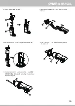
Страница 19: ...ightening the Cell Lock Nut j 8 Slot the cord connectors into the matching brackets as shown below 7 Tighten the cord connectors of new Cell with the main cords in the Cell Cover h 10 Reconnect the Ce...

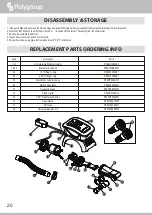
Страница 20: ...P58219221W05 P584150006W1 P58003689W05 1 31 19 24 23 20 18 29 13 15 30 14 31 28 27 15 13 16 17 18 11 12 26 25 31 14 29 30 24 21 20 19 23 22 10 28 1 9 DISASSEMBLY STORAGE 1 If the pool is filled with w...

Страница 21: ...between the Cell and filter pump if any for cracks or holes and replace as needed B1 Check that the Plastic Hose Clamp t is properly tightened B2 Check the O Ring f for damage and replace as needed B...

Страница 22: ......

Страница 23: ...e c mo localizar y resolver problemas visite support polygroupstore com Atenci n al cliente 1 888 919 0070 Puede ser necesario que nos env e parte del producto o el producto en su totalidad para inspe...

Страница 24: ...dor original del producto y se limita a la reparaci n o sustituci n del producto a discreci n de Polygroup Los da os consiguientes incluidas reclamaciones por p rdidas de agua qu micos para piscinas d...

Страница 25: ...ra posibles descargas el ctricas esta unidad debe montarse sobre una base en conformidad con las instrucciones de instalaci n 4 No entierre el cable Coloque el cable de forma que reduzca al m ximo la...

Страница 26: ...l GFCI donde las distancias sean por medida la ruta m s corta que seguir a el cable de alimentaci n de un aparato conectado al recept culo sin penetrar un suelo pared techo marco con puerta abisagrada...

Страница 27: ...83 m 3 05 m debe haber una connexion fija caja de distribuci n o una conexi n de trabas giratorias con un disyuntor diferencial 6 Conecte los cables de alimentaci n a una toma de corriente con conexi...

Страница 28: ...unicaciones Federales Este dispositivo cumple la Secci n 15 de las normativas de la FCC Su funcionamiento est sujeto a las dos condiciones siguientes 1 El dispositivo no debe ocasionar interferencias...

Страница 29: ...lmente en piscinas Como tal una piscina de agua salada no est realmente libre de cloro Simplemente utiliza un generador de cloro en vez de agregarle cloro directamente CA 120 V 75 vatios 1 25 amperios...

Страница 30: ...de conexi n de la celda Tubo conector para filtro skimmer Abrazadera de pl stico de la manguera Rejilla del filtro Entrada de la celda 1 1 1 1 1 2 1 1 1 1 1 1 1 2 2 2 1 Aro de fijaci n de 1 5 pulgada...

Страница 31: ...MANUAL DEL USUARIO 9 12 11 28 27 1 2 3 7 8 6 4 9 10 12 26 25 24 23 19 22 11 5 18 17 16 15 30 29 21 20 13 27 14 31...

Страница 32: ...preliminares 1 LEATODAS LAS INSTRUCCIONES CON ATENCI N y entienda bien todo lo necesario para armar este producto 2 Instale su piscina y bomba de filtraci n siguiendo las instrucciones del manual del...

Страница 33: ...les para conectarse al sistema de agua salada Serie de cartucho y skimmer para sistemas de filtraci n Serie de sistemas de filtraci n de arena BOMBAS DE FILTRACI N POLYGROUP N mero de serie P53RX06000...

Страница 34: ...n las horas restantes El indicador naranja de encendido modo 7 parpadea cada segundo Los indicadores del temporizador 2 mostrar n las horas restantes Bot n Funci n Acci n Indicador luminoso LED Imagen...

Страница 35: ...r sal en la p 14 El flujo de agua es normal No hay flujo de agua Examine la bomba de filtraci n Si la bomba de filtraci n funciona limpie el sensor de flujo de agua de la celda electrol tica s Consult...

Страница 36: ...horas para que la sal se disuelva completamente 5 Cuando toda la sal se haya disuelto encienda el sistema de agua salada C mo disminuir la sal Si ha agregado demasiada sal el indicador de estado de la...

Страница 37: ...6 4 57m x 91cm 15 x42 4 57m x 1 07m 15 x48 4 57m x 1 22m 18 x48 5 49m x 1 22m 14 x42 4 27m x 1 07m 16 x48 4 88m x 1 22m 157 5 x78 75 x39 37 4m x 2m x 1m 18 x9 x52 5 49m x 2 75m x 1 32m 106 592 631 102...

Страница 38: ...o de cloro es fundamental para mantener una piscina saludable Recomendamos verificar y ajustar el nivel de cloro de su piscina a diario Nivel ptimo de cloro El nivel ideal de cloro del agua de la pisc...

Страница 39: ...5 1 00 1 25 1 50 1 75 KGs 0 11 0 23 0 34 0 45 0 56 0 68 0 79 LIMPIEZA DEL SENSOR DEL FLUJO DE AGUA 1 Presione el bot n TEST en el conjunto del cable de alimentaci n GFCI k para apagar el sistema Luego...

Страница 40: ...t n TEST en el conjunto del cable de alimentaci n GFCI k para apagar el sistema Luego desench felo del tomacorriente 3 Separe la salida de la celda g de la manguera y el tubo de conexi n de la entrada...

Страница 41: ...los conectores del cable en los soportes correspondientes como se muestra a continuaci n 7 Apriete los conectores de cable de la nueva celda con los cables principales en la cubierta de celda h 10 Vue...

Страница 42: ...58PS00090W1 P58219221W05 P584150006W1 P58003689W05 1 31 19 24 23 20 18 29 13 15 30 14 31 28 DESARMADO Y ALMACENAMIENTO 1 Si la piscina est llena con agua use los tapones de servicio suministrados con...

Страница 43: ...ta grietas u orificios y reempl cela si fuera necesario B1 Compruebe que la abrazadera de pl stico de la manguera t est bien apretada B2 Compruebe si el aro f presenta da os y reempl celo si fuera nec...

Страница 44: ......

Отзывы: