start byte = 0x80 device type = 0x00 motor # and direction motor speed
Using the Motor Controller
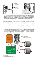
To set the speed and direction of a motor, send a four-byte command with the following
structure to the motor controller’s asynchronous serial input, labeled ‘2’ on the PCB.
You must send the four-byte command eight bits at a time (with no parity bit) at a
constant baud rate ranging from 1200 to 19200 baud. The serial bits must be
non-
inverted
, meaning that a zero is sent as a low
voltage, and a one is sent as a high voltage, as shown
in the diagram to the right. (The PC-connection
circuit on the previous page corrects the inverted
signal coming out of PC serial ports.)
Commands
sent to the serial input
must
conform to the above
format (described in detail below) or else the motor
controller and other devices connected to the serial
line may behave unexpectedly.
This motor controller
interface protocol
is compatible
with other Pololu serial devices such as our servo controller, so you can control
multiple Pololu serial devices on a single line.
The Four-byte Motor Controller Command
Byte 1: Start Byte.
This byte should
always
be 0x80 (128 in decimal) to signify the
beginning of a command. The start byte is the only byte with the highest bit (bit 7) set,
and it alerts all devices on the serial line that a new command is being issued. All
succeeding bytes sent down the serial line must have their highest bit cleared to zero.
Byte 2: Device Type.
This byte identifies the device type for which the command is
intended, and it should be 0x00 for commands sent to motor controllers. All devices
that are not
SMC01A
dual motor controllers ignore all subsequent bytes until another
start byte is sent.
Byte 3: Motor Number and Direction.
This byte
has three parts, as shown in the diagram to the right:
"
Bit 0 specifies the direction of the motor. Set
this bit to 1 to make the motor go forward; clear
the bit to make it go backward.
"
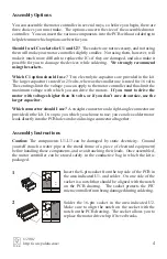
Bits 1-6 specify the motor number. If you are
using only two motors per serial line, you can
use the default values of 0 for motor M1 and 1 for
motor M2. If you want to control more than two
motors, use numbers in the range of 2 to 63, as
described in the section, “Controlling Multiple Motor Controllers with One Serial
Line”.
bit 0: direction
1 = forward
0 = reverse
bit 7
bit 0
0 x x x x x x x
bits 1-6: motor
number
bit 7: always 0
8
Pololu
10011010
start bit
stop bit
5V
0V
LSB
MSB
© 2001
http://www.pololu.com/


