7
Pololu
U3
SMC01A
C
1
M2
M2
11 22
M1
M1
MOTOR
BATTERY
G
N
D
O
U
T1
O
U
T2
ROBOT
CONTROLLER
OUT1: RESET
OUT2: CONTROL
Connecting the Motors.
Connect one or two motors to the pins labeled M1 and M2.
You probably don’t need to worry too much about the polarity, but the ‘+’ pins go
positive when the controller receives a “forward” command. If you find out that your
motors turn in different directions than you expect, you can flip the wiring or just
switch the forward and reverse commands on your robot controller program.
to 5V
(off C2+)
to serial
control
input (’2’)
to ground (’-’)
3
2
1
9
6
2
7
8
4
5
DB9 serial
port connector
R2
10k
R1
4.7k
Q1
2N2222
Bold
circles
indicate pads
that are connected
to 5V, which you can use
with the circuit shown on the left
SMC01A
C
2
C
1
U3
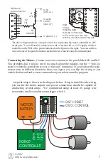
The above diagram shows a simple circuit for connecting the motor controller to a PC
serial port. You will need to connect one side of resistor R1 to a 5V supply, which is
available on the PCB at the points indicated on the figure to the right. You can solder a
wire onto one of the pads, but make sure that the wire touches only the intended pad.
A typical setup is shown in the diagram below. Keep in mind that the wiring
you use for the motor outputs and power connections should be capable of
conducting several amps. We recommend using at least 26 gauge wire
(remember, smaller numbers mean bigger wires!).
© 2001
http://www.pololu.com/


