


Pololu
2
Important Safety Warning
This kit is not intended for young children! Assembly of this kit
requires high-temperature soldering and the use of sharp cutting
tools. Some included components may become hot, leak, or explode
if used improperly. Pololu strongly recommends that you wear
safety glasses when building or working with
any
electronic
equipment. Children should use this kit only under adult supervision.
By using this product, you agree not to hold Pololu liable for any
injury or damage related to the use or to the performance of this
product. This product is not designed for, and should not be used
in, applications where the malfunction of the product could cause
injury or damage.
!
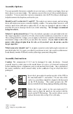
Parts List
The following components are the motor controller parts. Make sure to verify that all
components are included, and that you know which component is which. Each
component is labeled with its reference number and description. There are 11 parts in
the kit, including the PCB.
C1
Electrolytic
Capacitor
(2 options)
C2
Tantalum
Capacitor
CONNECTOR
8-pin female
header
(2 options)
PCB
Printed Circuit
Board
U1
PIC12C508A
Microcontroller
and Socket
U2
SN754410
Dual H-Bridge
and Socket
U3
LM2931
5-volt Regulator
© 2001
http://www.pololu.com/


