background image

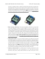
Pololu dual MC33926 motor

driver shield, assembled and

connected to an Arduino

Leonardo.

Pololu dual MC33926 motor

driver shield for Arduino, bottom

view with board dimensions.

1.a. Features

• Wide operating voltage range: 5 – 28 V

1

• Output current: 3 A continuous (5 A peak

2

) per motor

• Inputs compatible with both 5 V and 3.3 V systems

• PWM operation up to 20 kHz, which is ultrasonic and

allows for quieter motor operation

• Current sense voltage output proportional to motor

current (approx. 525 mV/A)

• Motor indicator LEDs show what the outputs are doing

even when no motor is connected

• Can be used with an Arduino or Arduino clone (through

shield headers) or other microcontroller boards (through
0.1″ header along the left side)

• When used as a shield, the motor power supply can

optionally be used to power the Arduino base as well

• Arduino pin mappings can be customized if the default

mappings are not convenient

Arduino library

[http://github.com/pololu/dual-mc33926-motor-

shield]

makes it easy to get started using this board as a

motor driver shield

• Reverse-voltage protection on motor supply

3

• Robust drivers:

◦ Transient operation (< 500 ms) up to 40 V

◦ Over-current limiting via internal PWM

◦ Over-temperature shutdown and hysteresis

◦ Under-voltage shutdown

◦ Output short-to-ground and short-to-Vcc protection

1

The board supports transient (< 500 ms) operation up to 40V. Operation from 5-8 V reduces maximum

continuous output current (driver performance is derated in this range).

2

Internal peak-current limiting gracefully reduces the output power at load currents above 6.5 A ± 1.5 A. See

the

MC33926 datasheet

[https://www.pololu.com/file/download/MC33926.pdf?file_id=0J233]

(1MB pdf) for more

Pololu Dual MC33926 Motor Driver Shield User’s Guide

© 2001–2017 Pololu Corporation

1. Overview

Page 3 of 30

Содержание MC33926

Страница 1: ...Power and Motors 10 3 d Programming Your Arduino 16 4 Using as a General Purpose Motor Driver 19 4 a Assembly for Use as a General Purpose Motor Driver 19 4 b Board Connections 20 5 Schematic Diagram...

Страница 2: ...s fully populated with its SMD components including the two MC33926 ICs as shown in the picture to the right stackable Arduino headers and terminal blocks for connecting motors and motor power are inc...

Страница 3: ...power the Arduino base as well Arduino pin mappings can be customized if the default mappings are not convenient Arduino library http github com pololu dual mc33926 motor shield makes it easy to get...

Страница 4: ...six large through holes to make your motor and motor power connections or you can break off a 12 1 section of the 0 1 header strip and solder it into the smaller through holes that border these larger...

Страница 5: ...An Arduino https www pololu com product 2191 is not included Pololu Dual MC33926 Motor Driver Shield User s Guide 2001 2017 Pololu Corporation 1 Overview Page 5 of 30...

Страница 6: ...pololu com product 2503 If you need technical support or have any feedback you would like to share you can contact us https www pololu com contact directly or post on our forum http forum pololu com...

Страница 7: ...lu com category 165 a star 32u4 prime Arduino Uno https www pololu com product 2191 both original and R3 Arduino Leonardo https www pololu com product 2192 Arduino Due https www pololu com product 219...

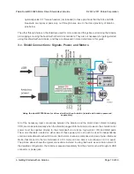
Страница 8: ...as an Arduino Shield 1 Stackable Arduino headers Before you can use this board as an Arduino shield you need to solder four of the five included Arduino header strips to the set of holes highlighted...

Страница 9: ...al blocks should be used or thick wires with high current connectors https www pololu com product 925 should be soldered directly to the board The smaller holes are intended only for 0 1 header pins n...

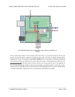
Страница 10: ...rduino and the motor driver shield including VDD are made automatically when the shield is plugged into the Arduino However the shield s motor power must be supplied directly to the shield itself via...

Страница 11: ...WM Motor 2 speed input Digital 12 SF or nSF Status flag indicator LOW indicates fault Analog 0 M1FB Motor 1 current sense output approx 525 mV A Analog 1 M2FB Motor 2 current sense output approx 525 m...

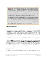
Страница 12: ...ield through other means such as from the Arduino or through the small VOUT pin can permanently damage both the Arduino and the shield only the large power traces on the right side of the shield are d...

Страница 13: ...er supply When the ARDVIN VOUT shorting block is in place the shield s reverse protected input power VOUT is connected to the Arduino s VIN pin When power is connected properly VOUT is essentially the...

Страница 14: ...he shield performance is derated and the maximum achievable continuous output current will be decreased according to the MC33926 datasheet H bridge MOSFET on resistances might increase by 50 in this q...

Страница 15: ...r motor has a stall current over the driver s continuous current rating of 3 A per channel we recommend you take extra steps to make sure that your motor will not be exposed to loads that will cause i...

Страница 16: ...h terminal to the case 2 Make your motor leads as thick and as short as possible and twist them around each other It is also beneficial to do this with your power supply leads 3 Route your motor and p...

Страница 17: ...0 i 400 i md setM1Speed i stopIfFault if abs i 200 100 Serial print M1 current Serial println md getM1CurrentMilliamps delay 2 for int i 400 i 400 i md setM1Speed i stopIfFault if abs i 200 100 Seria...

Страница 18: ...for feedback that the shield is working properly 64 65 66 67 68 69 70 71 72 73 74 75 76 77 78 79 80 81 82 83 84 85 86 87 88 89 90 91 92 93 94 Serial print M2 current Serial println md getM2CurrentMil...

Страница 19: ...as a General Purpose Motor Driver 1 Logic connections The 11 small holes along the left side of the board highlighted in red in the above diagram are used to interface with the motor drivers You can o...

Страница 20: ...iven high either through a connection to an I O line or by connecting it to the neighboring VDD pin With the exception of the pins labeled D2 1 2 and SF 1 2 all of the through holes not highlighted in...

Страница 21: ...wing table explains the board pins in detail See the MC33926 datasheet https www pololu com file download MC33926 pdf file_id 0J233 1MB pdf for even more detailed information about these pins Pololu D...

Страница 22: ...tion input MxFB Current sense output The pin voltage is roughly 525 mV per amp of output current Note that the voltage on this pin can exceed 3 3 V at high currents which might make it unsafe to conne...

Страница 23: ...clear any latched faults Note that the disable lines from both drivers are tied together See Section 6 b for information on how to individually access the disable pins this is typically not necessary...

Страница 24: ...buses when not used with an Arduino The shield must be supplied with 5 to 28 V through the large VIN and GND pads on the right side of the board A high side reverse voltage protection MOSFET prevents...

Страница 25: ...r controlling device should be supplied to the VDD pin This will typically be between 2 5 and 5 V Please see the MC33926 datasheet and Section 3 c for more power considerations and for information abo...

Страница 26: ...for Arduino PDF of schematic dual MC33926 motor driver shield schematic https www pololu com file download dual_mc33926_shield_schematic pdf file_id 0J559 350k pdf Pololu Dual MC33926 Motor Driver Shi...

Страница 27: ...og inputs for reading sensors With this in mind we designed the shield to have break points in the connection between the Arduino pins and the motor drivers It is easy to cut the connections at these...

Страница 28: ...mply use a knife to cut the trace between the appropriate pair of holes on the underside of the PCB there is no connection to cut on the topside of the PCB and run a wire from a different Arduino pin...

Страница 29: ...information There are two pairs of 0 1 spaced holes on the shield labeled D2 1 2 and SF 1 2 These pairs are connected on the underside of the PCB by a thin trace with the holes labeled M1 connecting...

Страница 30: ...ns is severed only M1SF will have the required pull up resistor and the protection resistor between it and the logic connections you will need to add a separate pull up resistor and protection resisto...

Отзывы: