


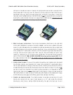


optionally solder 0.1″ female headers (not included) to these pins. Note that the SCL and SDA
breakouts are top-layer pads only, not through-holes, due to the close proximity of Arduino
pins below.
The other through-holes on the shield are used for more advanced things like customizing the Arduino
pin mappings or using the board with other microcontrollers. They are not necessary for getting started
using this shield with an Arduino, and they are discussed in more detail later in this guide.
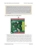
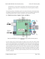
3.c. Shield Connections: Signals, Power, and Motors
Using the dual MC33926 motor driver shield with an Arduino (shield and Arduino powered
separately).
All of the necessary logic connections between the Arduino and the motor driver shield, including
VDD, are made automatically when the shield is plugged into the Arduino. However, the shield’s motor
power must be supplied directly to the shield itself via its large, high-current VIN and GND pads.
The motor channels, located on either side of these power pins, can each be used to independently
control a bidirectional brushed DC motor. Each motor channel is comprised of a pair of pins—MxA and
MxB—that connect to the two terminals of a DC motor and can deliver a continuous 3 A (5 A peak).
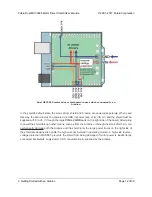
The picture above shows the typical connections involved in using this board as an Arduino shield. In
the depicted configuration, the Arduino is powered separately from the shield, such as through its USB
connector or power jack.
Pololu Dual MC33926 Motor Driver Shield User’s Guide
© 2001–2017 Pololu Corporation
3. Getting Started with an Arduino
Page 10 of 30


