DD-75-181 R(2)
Y.T.13.07.17
16
Check/ tighten if required
Check
Check/ tighten if required
Check + Grease
Check
Check + Lubricate
Check
Check (free movement)
Check
Check (free movement)
Check + Adjust
Check / replace if required
Check
Check
Check
Check
Check
Check + Clean Dust
Check + Clean Dust
Check
Check +Clean Dust
Check
Anchoring nuts and bolts
Top cover / Lock/ Seals and drainage
Rotor arms/ bolts
Rotor bottom bearing
Rotor coupling and connections
Main rotor shaft
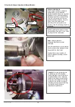
Clamp spring, damper arm bearing (manual type)
Lock levers and springs
Solenoids
Ratchet mechanism and spring
Hydraulic Damper (Manual type)
Hydraulic damper arm bearing
Motor (Motor driven type)
Motor pulley and drive belt (Motor driven type)
Mechanism mounting nuts and bolts
Mechanism Bearings
Power connections, wiring and grounding
Electronic Control Board
Positioning photosensor
Wiring and connectors
Motor Driver Board (Motor driven type)
Indicators and buzzer
12 Month
12 Month
12 Month
12 Month
12 Month
12 Month
12 Month
12 Month
12 Month
12 Month
12 Month
12 Month
12 Month
12 Month
12 Month
12 Month
12 Month
12 Month
12 Month
12 Month
12 Month
12 Month
General
Mechanism Assembly
Electrical Components
Full Height Turnstiles
Maintenance Item
Period
Recommended Action
7.2 Trouble Shooting and Repair Guide
7.1.2 Periodic Maintenance by Technical Service Personnel
Description of Fault
Possible Cause
Recommended Action
No power. (indicators, buzzer,
locks off)
Rotor free wheels when power
is on
Note: Ensure Emg. terminal is
not activated and dip switches
3 and 4 are off
Turnstile does not allow
passage when input contact is
given-buzzer heard
Rotor/arms do not return to
center (standby) position
following a passage
Rotor bounces back and forth
following a rotation, fails to
settle in rest position smoothly
1.
No AC power supplied to unit.
2.
Loose power cable
3.
Blown fuse
4.
Faulty power supply unit
1.
Loose solenoid or photo sensor
connector
2.
Faulty photo sensor
3.
Faulty solenoid
4.
Faulty control board
Note: periodic beep and red indicators
indicate a loose or faulty photo sensor.
1.
Restricted lock lever movement
(due to foreign object such as cable,
gummed lubricant etc.)
2.
Sticky solenoid
3.
Faulty control board
4.
Misaligned/bent photo sensor in
motorized units
1.
Loose or broken clamp spring
2.
Over damped hydraulic damper
setting
1.
Under damped hydraulic damper
setting
2.
Worn out / faulty hydraulic damper
1.
Restore AC power.
2.
Connect power cable.
3.
Replace fuse (see 2.2)
4.
Replace power supply unit
1.
Re-insert connector
2.
Replace photo sensor
3.
Replace solenoid.
4.
Replace control board
1.
Repair lever mechanism
2.
Replace solenoid
3.
Replace control board
4.
Adjust photo sensor (motorized
units)
1.
Re-install / replace clamp spring
2.
Adjust hydraulic damper (see 5.5)
1.
Adjust hydraulic damper (see 5.5)
2.
Replace and adjust hydraulic
damper


