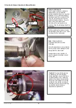
5.2 Control Board Connections
1. Loosen wire entry hole
cover screw.
2.
lnsert Control cable.
Enable/ Disable (lnhibit)
terminal (A-B or B-A)
lnhibits passage when
connected to Gnd
(common)
Caution!
Pay attention to
pin markers when inserting
a new microprocessor into
socket. Firmware number
must be correct.
Caution!
Match socket
and cable tumber tags
when replacing board
and other parts!
3.
Connect cable leads into
the screw type connector.
Passage Confirmation Relay
��� } NO (Normally
B-A
Open) Dry Contact
Com
Control lnput Terminal
INA
}
iN B
NO (Normally
Reset
Open) Dry
Gnd (Common) Contact
Emg (Emergency): NC
(Normally Closed Contact) *
Note:
Control contact duration of 1 second or less is recommended for optimal flow rate.
* Emg (Emergency) terminal is controlled by NO (Normally Open) contact in units produced before April 2016.
DD-75-181 R(2)
10
Y.T.13.07.17


