9.8
REAR SUSPENSION
REAR SUSPENSION ADJUSTMENTS
AND SETTINGS
Rear Suspension Adjustment Procedures
It is a good idea to have customers break the suspension in for
approximately 150 miles (240 km) before fine tuning
adjustments are made.
All settings will vary from rider to rider, depending on rider
weight, vehicle speed, riding style, and trail conditions. We
recommend starting with factory settings and then customizing
each adjustment individually to suit rider preference. The
machine should be methodically tested under the same
conditions after each adjustment (trail and snow conditions,
vehicle speed, riding position, etc.) until a satisfactory ride is
achieved. Adjustments should be made to one area at a time, in
order to properly evaluate the change.
The purpose of the front rear scissor stop (FRSS) is to control the
bump attitude of the rear suspension. As the front torque arm
(FTA) hits the bump, it forces the rear scissor to collapse a
predetermined amount, depending on the FRSS block position.
This accomplishes two important things, it allows a lighter
spring rate on the FTA because it can borrow spring rate from
the rear torsion springs; and it prepares the rear portion of the
suspension for the bump, reducing secondary kick back.
The FRSS is made of a resilient material allowing smooth action
and preventing any suspension component damage.
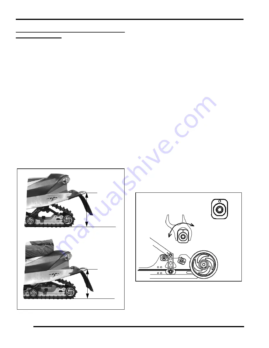
Setting the Rear Suspension Ride Height
1.
To set up the rear suspension torsion spring preload,
measure the distance between the ground and rear bumper
with out the rider on the seat and the suspension at full
extension. This can be achieved by lifting the rear of the
machine so that the suspension is off the ground and
carefully setting the machine down. Write this down as
measurement “X”.
2.
Have the rider in full gear drop down on the seat, work the
suspension slightly by bouncing up and down and sit in the
seated riding position. With the rider in the seated position
measure from the ground to the bumper in the same spot as
you did for measurement “X” and write it down as
measurement “Y”.
3.
To determine the correct ride height, subtract measurement
X from measurement Y. (X - Y = ride height).
4.
The ideal ride height is:
• IQ 121 = 4-5
”
(10-13cm)
• M-10 128/136 = 3-4
”
(8-10cm)
• IQ Switchback/ IQ RMK= 5
”
(13cm)
• EDGE RMK/EDGE = 4
”
(10cm)
• Widetrak = 1.5
”
(4cm)
5.
Adjust for the desired ride height by rotating the torsion
spring cams located on the rear of the torsion spring.
If the rear suspension ride height can not be adjusted to the cor-
rect dimension, optional torsion springs may be required. This
is only an initial setup, and final spring preload may vary based
on rider preference and riding conditions.
Scissor Stop Adjustments
The RRSS controls weight transfer from the rear suspension to
the skis. It also influences the stiffness of the ride by controlling
the amount of coupling action between the front and rear torque
arms. To decrease weight transfer, the RRSS should be set in the
high position.
The RRSS can be totally removed for maximum weight transfer.
However, unless the torsion springs and rear shock valving are
X
Y
ROTATE
HIGH
LOW
LOW
MEDIUM
Содержание 340 LX 2007
Страница 4: ......
Страница 40: ...NOTES MODEL SPECIFICATIONS 1 36...
Страница 51: ...2 11 GENERAL 2 SPECIAL TOOLS Special Tools...
Страница 52: ...2 12 GENERAL...
Страница 53: ...2 13 GENERAL 2...
Страница 54: ...2 14 GENERAL...
Страница 80: ...NOTES MAINTENANCE 3 26...
Страница 91: ...4 11 FUEL DELIVERY 4 Throttle Opening Vs Fuel Flow VM only...
Страница 104: ...NOTES FUEL DELIVERY 4 24...
Страница 114: ...5 10 ENGINE 500 600 Touring WideTrak LX Touring WideTrak...
Страница 146: ...NOTES ENGINE 5 42...
Страница 170: ...NOTES CLUTCHING 6 24...
Страница 214: ...NOTES FRONT SUSPENSION STEERING 8 20...
Страница 259: ...10 11 CHASSIS HOOD 10...
Страница 260: ...NOTES CHASSIS HOOD 10 12...
Страница 272: ...11 12 BATTERY ELECTRICAL SYSTEMS ELECTRIC START GEN II EDGE System Schematic...
Страница 276: ...11 16 BATTERY ELECTRICAL SYSTEMS ELECTRIC START IQ CARBURETED CFI System Schematic 600 HO Carbureted...
Страница 277: ...11 17 BATTERY ELECTRICAL SYSTEMS 11 System Schematic 600 700 CFI...
Страница 286: ...11 26 BATTERY ELECTRICAL SYSTEMS Chassis Relay...
Страница 288: ...11 28 BATTERY ELECTRICAL SYSTEMS Vehicle Speed Sensor...
Страница 293: ...11 33 BATTERY ELECTRICAL SYSTEMS 11 CFI Power System CFI Ignition Injection Power...
Страница 294: ...11 34 BATTERY ELECTRICAL SYSTEMS CFI Crank Position System CFI Safety Stop System...
Страница 295: ...11 35 BATTERY ELECTRICAL SYSTEMS 11 CFI Full Load Fuel Injectors CFI Part Load Fuel Injectors...
Страница 296: ...11 36 BATTERY ELECTRICAL SYSTEMS CFI Chassis Power CFI Ignition Coils...
Страница 297: ...11 37 BATTERY ELECTRICAL SYSTEMS 11 CFI TBAP Sensor CFI TPS Engine Temp Sensors...
Страница 298: ...11 38 BATTERY ELECTRICAL SYSTEMS CFI Exhaust Solenoid CFI Knock Sensor...
Страница 299: ...11 39 BATTERY ELECTRICAL SYSTEMS 11 CFI Fuel Pump CFI Diagnostic Connections...
Страница 300: ...11 40 BATTERY ELECTRICAL SYSTEMS CFI MFD Circuits CFI MFD Power Circuits...
Страница 301: ...11 41 BATTERY ELECTRICAL SYSTEMS 11 CFI Fuel Level Circuit CFI Vehicle Speed Circuit...
Страница 302: ...11 42 BATTERY ELECTRICAL SYSTEMS CFI Mode Set Switch CFI PERC Switch...
Страница 318: ...12 1 Wiring Diagrams 2007 340 550 GEN II EDGE Models...
Страница 319: ...12 2 Wiring Diagrams 2007 Wide Trak...
Страница 320: ...12 3 Wiring Diagrams 2007 500 XCSP...
Страница 321: ...12 4 Wiring Diagrams 2007 600 HO Carbureted 1 of 2...
Страница 322: ...12 5 Wiring Diagrams 2007 600 HO Carbureted 2 of 2...
Страница 323: ...12 6 Wiring Diagrams 2007 600 HO Carbureted Hood Harness...
Страница 324: ...12 7 Wiring Diagrams 2007 600 700 CFI 1 of 2...
Страница 325: ...12 8 Wiring Diagrams 2007 600 700 CFI 2 of 2...
Страница 327: ...12 10 Wiring Diagrams...


