background image

4.5

ELECTRONIC FUEL INJECTION

4

9924125 - 2013 

RANGER

 RZR / RZR S / RZR 4 Service Manual

© Copyright 2012 Polaris Sales Inc.

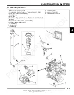
EFI System Exploded View

1. Electronic Control Unit (ECU)

2. Temperature / Manifold Absolute Pressure Sensor (T-MAP)

3. Crankshaft Position Sensor (CPS)

4. Fuel Injectors

5. Fuel Filter

6. Fuel Pump / Regulator / Fuel Level Sender (located in fuel tank)

7. Fuel Rail

8. Engine Coolant Temperature Sensor (ECT)

9. Throttle Position Sensor (TPS)

10. Throttle Body

11. Ignition Coil

12. Spark Plugs

1

2

3

4

5

6

7

8

9

10

11

13. Spark Plug Wires
14. Idle Air Control (IAC)

14

15. Camshaft Phase Sensor

15

12

13

PRELIMINARY 

VERSION

Содержание 2013 RANGER RZR

Страница 1: ...UBLICATION NUMBERS 1 4 REPLACEMENT KEYS 1 4 SPECIAL TOOLS 1 5 GENERAL SPECIFICATIONS 1 6 GENERAL 2013 RANGER RZR EPS 1 6 DETAILED 2013 RANGER RZR EPS 1 7 GENERAL 2013 RANGER RZR S INT L 1 8 DETAILED 2...

Страница 2: ...ive E 4x4 Shaft IRS G 4x4 Chain rear shaft front H 4x4 Shaft IRS J 2x4 Swing arm Manual N 4x4 Shaft ADC P 2x4 IRS Manual R 6x6 Shaft IRS T 4x4 Shaft Trailing Arm X 4x4 Shaft EBS Displacementinccdivide...

Страница 3: ...V refer to the vehicle identification number VIN and engine serial number The VIN can be found stamped on the rear upper frame rail behind the left rear fender near the air box see Figure 1 1 The engi...

Страница 4: ...he first two digits on the original key and refer to the chart to the right for the proper part number Model Model No Owner s Manual Parts Manual 2013 RANGER RZR R13VH76AC AD AN AS 9924099 9924104 201...

Страница 5: ...tory while other tools may be substituted with a similar tool if available Polaris recommends the use of Polaris Special Tools when servicing any Polaris product Dealers may order special tools throug...

Страница 6: ...cm Cargo Box Capacity 300 lbs 136 kg Maximum Weight Capacity Payload 740 lbs 335 6 kg Includesrider s cargo accessories and trailer tongue weight Hitch Towing Capacity 1500 lbs 680 kg Hitch Tongue Ca...

Страница 7: ...12 Volt Relays Chassis EFI Fan Fuel Pump EPS Circuit Breaker Fan Motor 20 Amp Fuses Fuse Relay Box Drive Fuel Pump 10 Amp Lights EFI Accessory 20 Amp Fuses Power Fuse Holder EFI 20 Amp Chassis EPS 30...

Страница 8: ...go Box Capacity 300 lbs 136 kg Maximum Weight Capacity Payload 740 lbs 335 6 kg Includesrider s cargo accessories and trailer tongue weight Hitch Towing Capacity 1500 lbs 680 kg Hitch Tongue Capacity...

Страница 9: ...is EFI Fan Fuel Pump Circuit Breaker Fan Motor 20 Amp Fuses Fuse Relay Box Drive Fuel Pump 10 Amp Lights EFI Accessory 20 Amp Fuses Power Fuse Holder EFI 20 Amp Chassis 30 Amp Drivetrain Transmission...

Страница 10: ...ox Capacity 300 lbs 136 kg Maximum Weight Capacity Payload 900 lbs 408 kg Includesrider s cargo accessories and trailer tongue weight Hitch Towing Capacity 1500 lbs 680 kg Hitch Tongue Capacity 150 lb...

Страница 11: ...elays Chassis EFI Fan Fuel Pump EPS Circuit Breaker Fan Motor 20 Amp Fuses Fuse Relay Box Drive Fuel Pump 10 Amp Lights EFI Accessory 20 Amp Fuses Power Fuse Holder EFI 20 Amp Chassis EPS 30 Amp Drive...

Страница 12: ...ORMATION 9924125 2013 RANGER RZR RZR S RZR 4 Service Manual Copyright 2012 Polaris Sales Inc MISC SPECIFICATIONS AND CHARTS Conversion Table C to F C x 9 5 32 F F to C F 32 x 5 9 C P R E L I M I N A R...

Страница 13: ...69 7 16 14 30 40 50 69 70 97 7 16 20 35 48 55 76 80 110 1 2 13 50 69 75 104 110 152 1 2 20 55 76 90 124 120 166 Bolt Size Grade 4 6 4 8 8 8 8 9 10 9 12 9 ft lbs Nm Dry Threads M3 3 5 5 7 1 1 3 1 5 2 1...

Страница 14: ...GENERAL INFORMATION 9924125 2013 RANGER RZR RZR S RZR 4 Service Manual Copyright 2012 Polaris Sales Inc SAE Tap Drill Sizes Metric Tap Drill Sizes Decimal Equivalents P R E L I M I N A R Y V E R S I...

Страница 15: ...OIL AND FILTER SERVICE 2 16 ENGINE BREATHER HOSE INSPECTION 2 17 ENGINE AND TRANSMISSION MOUNTS 2 17 COMPRESSION AND LEAKDOWN TEST 2 17 EXHAUST SPARK ARRESTOR 2 18 TRANSMISSION AND GEARCASES 2 19 TRA...

Страница 16: ...WHEEL HUB INSPECTION 2 33 WHEEL TOE ALIGNMENT INSPECTION 2 34 WHEEL TOE ADJUSTMENT 2 34 SUSPENSION STANDARD 2 35 SPRING PRELOAD ADJUSTMENT 2 35 SUSPENSION FOX 2 36 SPRING PRELOAD ADJUSTMENT 2 36 SHOCK...

Страница 17: ...tely if the oil level begins to rise Monitor the oil level and if it continues to rise discontinue use and determine the cause or see your dealer Break In Period The break in period consists of the fi...

Страница 18: ...test E Engine Breather Filter if equipped 25 H Monthly 250 400 Inspect replace if necessary E Engine Oil Change Break In Period 25 H 1 M 250 400 Perform a break in oil change after the first 25 hours...

Страница 19: ...00 H 12 M 1000 1600 Check for leaks at fill cap fuel line rail and fuel pump Replace lines every two years E Spark Plug 100 H 12 M 1000 1600 Inspect replace as needed Drive Belt 100 H 12 M 1000 1600 I...

Страница 20: ...n dipstick Change after 1st month or first 25 hours of operation 100hours thereafter Change more often 25 hours in severe duty conditions or short trip cold weather operation 2 Engine Coolant Polaris...

Страница 21: ...lubricant until it is visible at the fill hole threads Initial level check at 25 hours change according to intervals 5 Rear Gearcase Polaris ATV Angle Drive Fluid ADF Add lubricant until it is visibl...

Страница 22: ...d on the front propshaft yoke Apply grease until all traces of water have been purged out at each of these areas Item Recommended Lube Method Frequency Front Propshaft Yoke s Polaris Premium U Joint G...

Страница 23: ...1 Gal 4 Count 2878070 AGL Plus Gearcase Lubricant 2 5 Gal 2 Count 2876160 ATV Angle Drive Fluid 8 oz 12 Count 2872276 ATV Angle Drive Fluid 2 5 Gal 2 Count 2877922 Demand Drive Plus Quart 2877923 Dem...

Страница 24: ...cotter pins are in place Refer to specific fastener torques listed in each chapter Shift Cable Inspection Adjustment Shift cable adjustment may be necessary if symptoms include No AWD or gear position...

Страница 25: ...vent lines for signs of wear deterioration damage or leakage Replace every two years 2 Be sure vent lines are routed properly and secured with cable ties IMPORTANT Ensure lines are not kinked or pinch...

Страница 26: ...cause a delay in throttle response especially at low engine speed The throttle may also not open fully If the throttle cable has no freeplay the throttle may be hard to control and the idle speed may...

Страница 27: ...ke duct and tighten the hose clamp 10 Reinstall the air intake box and 2 push rivets 11 Reinstall the cargo box all fasteners and reconnect the taillight harness 12 Reinstall the rear service panel an...

Страница 28: ...ring over the end of the filter NOTE Apply a small amount of general purpose grease to the sealing edges of the filter and the air box cap seal before installing 3 Install the filter into the air box...

Страница 29: ...ck is inserted all the way into the filler tube to keep the angle and depth of dipstick consistent 7 Remove dipstick and check to see that the oil level is in the SAFE range Add oil as indicated by th...

Страница 30: ...9 Place shop towels beneath oil filter Using Oil Filter Wrench PU 50105 and a 3 8 extension turn the oil filter counter clockwise to remove it 10 Using a clean dry cloth clean filter sealing surface o...

Страница 31: ...de of the airbox to the engine valve cover NOTE Make sure line is not kinked or pinched Engine and Transmission Mounts Periodically inspect engine and transmission mounts for cracks or damage Refer to...

Страница 32: ...d damage Replace if needed 4 Reinstall the arrestor and torque the screw to specification WARNING Do not clean spark arrestor immediately after the engine has been run as the exhaust system becomes ve...

Страница 33: ...specification Gearcase Lubricant Capacity Fill Plug Torque Drain Level Check Plug Torque Transmission Main Gearcase AGL Plus Gearcase Lubricant 24 oz 710 ml 40 50 ft lbs 54 68 Nm 30 45 in lbs 3 5 Nm...

Страница 34: ...gh the drain holes in the skid plate Transfer Case Lubricant Change 1 Remove the fill plug and the level check plug refer to Transfer Case Lubricant Level Check 2 Place a drain pan under the transfer...

Страница 35: ...ion 5 Add the recommended fluid through the fill plug hole Maintain the fluid level at the bottom of the fill plug hole when filling the Main Gearcase Do not overfill 6 Reinstall the fill level plug a...

Страница 36: ...he fluid level 3 Add the recommended fluid as needed Maintain the lubricant level even with the bottom threads of the fill plug hole 4 Reinstall the fill plug and torque to specification Lubricant Cha...

Страница 37: ...ucted Lubricant Level Check The fill plug is located on the right side of the rear gearcase Maintain the fluid level even with the bottom of the threads of the fill plug hole 1 Position the vehicle on...

Страница 38: ...emove the drain plug and allow the lubricant to drain completely 4 Clean the drain plug 5 Reinstall the drain plug with new O ring and torque to specification 6 Add the recommended lubricant Maintain...

Страница 39: ...bottle With the engine at operating temperature the coolant level should be between the upper and lower marks on the coolant recovery bottle If not perform the following procedure 1 Position the vehic...

Страница 40: ...and impurities which build up in the system Straight water or antifreeze may cause the system to freeze corrode or overheat Cooling System Pressure Test Refer to Chapter 3 for cooling system pressure...

Страница 41: ...erneath the radiator fitting on the front RH side of the vehicle 4 Drain the coolant from the radiator by removing the lower coolant hose from the radiator as shown Properly dispose of the coolant 5 A...

Страница 42: ...ion on the wheel hub Be sure the valve stem is toward the outside and rotation arrows on the tire point toward forward rotation 4 Attach the wheel nuts and finger tighten them 5 Carefully lower the ve...

Страница 43: ...Inspect the drive shaft boots for damage tears wear or leaking grease If the boots exhibit any of these symptoms they should be replaced Refer to Chapter 7 for drive shaft boot replacement WARNING Ope...

Страница 44: ...ery out of the vehicle WARNING CALIFORNIA PROPOSITION 65 WARNING Batteries battery posts terminals and related accessories contain lead and lead compounds and other chemicals known to the State of Cal...

Страница 45: ...er to Chapter 10 Electrical for off season storage procedures Battery Charging Maintenance Free Refer to Chapter 10 Electrical for charging procedure Spark Plug Service 1 Remove the rear service panel...

Страница 46: ...r if the incorrect spark plug is used 10 Apply anti seize compound to the spark plug threads 11 Install spark plugs and torque to specification 12 Install the plug caps to the appropriate cylinder by...

Страница 47: ...feels rough inspect the following components Tie Rod Ends Steering Shaft U Joints Steering Gearbox Tie Rod End Wheel Hub Inspection To check for play in the tie rod end grasp the steering tie rod pul...

Страница 48: ...ement A The difference between measurements A and B is the vehicle toe alignment The recommended vehicle toe tolerance is 1 8 to 1 4 3 to 6 cm toe out This means the measurement at the front of the ti...

Страница 49: ...e on a level surface and stop the engine 2 Raise and safely support front or rear of vehicle off the ground to allow the suspension to fully extend NOTE The tires should not be touching the ground 3 T...

Страница 50: ...ing 3 Once you have obtained the correct preload hold the lower adjustment ring while tightening the upper adjustment ring to lock them in place IMPORTANT Always return the spring preload to the facto...

Страница 51: ...until it stops the damping is in the fully closed position Turn the clicker clockwise to increase compression damping Turn the clicker counter clockwise to decrease compression damping NOTE The factor...

Страница 52: ...wer than the MIN level line add brake fluid until it reaches the MAX level line 5 Install the reservoir cap and apply the brake pedal forcefully for a few seconds and check for fluid leakage around th...

Страница 53: ...LINDER HEAD ASSEMBLY EXPLODED VIEW 3 26 ROCKER ARMS PUSH RODS 3 27 CYLINDER HEAD REMOVAL 3 27 CYLINDER HEAD INSPECTION WARP 3 28 VALVE SEAL SPRING SERVICE ON ENGINE 3 28 CYLINDER HEAD DISASSEMBLY 3 29...

Страница 54: ...3 2 ENGINE COOLING 9924125 2013 RANGER RZR RZR S RZR 4 Service Manual Copyright 2012 Polaris Sales Inc ENGINE SPECIFICATIONS Crankcase Exploded Views P R E L I M I N A R Y V E R S I O N...

Страница 55: ...3 3 ENGINE COOLING 3 9924125 2013 RANGER RZR RZR S RZR 4 Service Manual Copyright 2012 Polaris Sales Inc Oil Pump Gears Engine Cover Exploded View P R E L I M I N A R Y V E R S I O N...

Страница 56: ...4 ENGINE COOLING 9924125 2013 RANGER RZR RZR S RZR 4 Service Manual Copyright 2012 Polaris Sales Inc Stator Cover Starter Water Pump Lubrication System Exploded View P R E L I M I N A R Y V E R S I O...

Страница 57: ...3 5 ENGINE COOLING 3 9924125 2013 RANGER RZR RZR S RZR 4 Service Manual Copyright 2012 Polaris Sales Inc Cylinder Cylinder Head Piston Exploded View P R E L I M I N A R Y V E R S I O N...

Страница 58: ...3 RANGER RZR RZR S RZR 4 Service Manual Copyright 2012 Polaris Sales Inc Engine EFI Sensors Valve Cover General Components Exploded View NOTE See chapter 4 for more information on the EFI System P R E...

Страница 59: ...0 18 2 24 5 2 7 Magneto Cover 6 mm 96 12 10 85 1 35 Oil Baffle Weldment 5 mm 60 6 6 8 0 68 Oil Drain Bolt Crankcase 12 mm 192 24 21 7 2 7 16 21 7 Oil Fill Tube Bolt 5 mm 50 5 5 64 0 56 Oil Filter Pipe...

Страница 60: ...nter Balance End Play 0 005 0 127 mm Cylinder Head Cylinder Head Surface warp limit 0 00394 0 1 mm Cylinder Head Standard height 3 478 88 35 mm Valve Seat Valve Seat Contacting Width Intake 0 0472 0 0...

Страница 61: ...Pin Bore 0 00047 0 00024 0 012 0 006 mm Piston Pin Degree of Fit Piston pin must be push fit by hand at 68 F 20 C Piston Connecting Rod Crankshaft Engine Specifications Main Components Piston Connecti...

Страница 62: ...ESSURE HOSE 2871043 FLYWHEEL PULLER 2870390 PISTON SUPPORT BLOCK PU 45497 1 CAM GEAR SPRING INSTALLATION KIT PU 45497 2 CAM GEAR TOOTH ALIGNMENT TOOL PU 45498 CAM SPANNER WRENCH PU 45838 GEAR HOLDER P...

Страница 63: ...eals Pressure Cap Test 1 Remove the front hood see Warning under Cooling System Pressure Test 2 Remove pressure cap and test using a pressure cap tester commercially available 3 The pressure cap relie...

Страница 64: ...Radiator Radiator Shroud Radiator Pressure Cap Fan Motor Water Pump Cover Thermostat Housing Outlet Hose Inlet Hose Filler Neck To Top Fitting on Filler Neck To Lower Fitting on Filler Neck Bypass Ho...

Страница 65: ...e the front bumper see Chapter 5 7 Remove the upper engine outlet hose and recovery hose from the top of the radiator 8 Remove the 2 upper radiator retaining bolts and the 4 bolts retaining the lower...

Страница 66: ...rt the engine and let it idle for 5 10 minutes or until the thermostat opens and allows coolant to flow through the system 7 Squeeze the coolant lines by hand to help purge the system of air 8 Slightl...

Страница 67: ...the system should be purged of air 11 Stop the engine and let cool top off the radiator filler neck with coolant If you hear or see a glug at the filler neck or there is a dropping of the coolant lev...

Страница 68: ...iced or removed with the engine installed Starter Motor Drive Cylinder Head Cylinder Piston Rings Rocker Arms Water Pump The following components require engine removal for service Flywheel Alternator...

Страница 69: ...oil to bypass the filter element At this point the oil is supplied to the main oil galley through a crankcase passage Oil is then diverted three ways from the main oil galley with the first path ente...

Страница 70: ...ol down before attempting to perform any work 2 Clean work area 3 Thoroughly clean the engine and chassis 4 Drain appropriate lubricant s If servicing the engine drain engine oil If servicing the tran...

Страница 71: ...he spark plugs and disconnect the ignition coil harness IMPORTANT Mark or note which ignition coil wire goes to which cylinder and ignition coil post The engine will misfire if the spark plug wires ar...

Страница 72: ...emove the remaining bolt attaching the airbox to the frame see photo 25 Remove the airbox and throttle body from the vehicle as an assembly Take care in not allowing the throttle cable to bend excessi...

Страница 73: ...ted incorrectly PTO Gray MAG Black 27 Disconnect the fuel line from the fuel injector rail by slightly squeezing the lock tabs and gently pushing the connector lock out To separate the lines pull the...

Страница 74: ...ss 33 Disconnect the transmission speed sensor harness 34 Disconnect the cam phase sensor connector 35 Remove the castle nuts from both rear wheel hubs 36 Remove the through bolt that attaches the upp...

Страница 75: ...sensor harness and the bypass coolant hose 40 Loosen the hose clamp and remove the lower coolant hose from the water pump cover inlet and drain coolant into a suitable container 41 Remove the filler n...

Страница 76: ...le engine hoist is the only recommended method for removing and installing the engine transmission rear gearcase assembly 47 Using an engine hoist hook a chain between the engine transmission mounting...

Страница 77: ...e the engine transmission rear gearcase assembly has been removed from the vehicle the engine and transmission will need to be separated to allow engine servicing Use the following procedure to separa...

Страница 78: ...is Sales Inc ENGINE DISASSEMBLY AND INSPECTION Cylinder Head Assembly Exploded View Push Rods Hydraulic Lifters Valves Cylinder Head Coolant Bleeder Springs Spring Retainers Rocker Arms Retainer Locks...

Страница 79: ...n be visually checked for straightness while they are installed in the engine by rotating them with the valve closed Push rods can also be checked with a dial indicator or rolled across a flat surface...

Страница 80: ...head 1 Having already removed the valve cover rocker arms and pushrods align the cylinder to be worked on at top dead center TDC Install the Valve Pressure Hose PU 45652 into the spark plug hole Hook...

Страница 81: ...e spring if measurement is out of specification 4 Remove valve guide seals IMPORTANT It is recommended to replace seals whenever the cylinder head is disassembled Hardened cracked or worn valve seals...

Страница 82: ...ree places then rotate 90 degrees and measure again six measurements total Compare to specifications 5 Measure valve guide C inside diameter at the top middle and end of the guide using a small hole g...

Страница 83: ...st be replaced Follow the manufacturers instructions provided with the valve seat cutters in the commercially available cylinder head reconditioning kit Abrasive stone seat reconditioning equipment ca...

Страница 84: ...w times 7 Remove valve and check where the Prussian Blue indicates seat contact on the valve face The valve seat should contact the middle of the valve face or slightly above and must be the proper wi...

Страница 85: ...the valves one at a time to maintain proper order 1 Apply engine oil to valve guides and seats 2 Coat valve stem with molybdenum disulfide grease or synthetic engine oil 3 Install valve carefully with...

Страница 86: ...with Piston Support Block PN 2870390 Valve Lifter Removal Inspection 1 Remove the valve lifters by reaching into the crankcase and pushing the lifter up through the lifter bore by hand 2 Thoroughly cl...

Страница 87: ...g may lose radial tension 3 Remove top compression ring Using a piston ring pliers Carefully expand ring and lift it off the piston CAUTION Do not expand the ring more than the amount necessary to rem...

Страница 88: ...a telescoping gauge or a dial bore gauge Measure in two different directions front to back and side to side on three different levels 1 2 down from top in the middle and 1 2 up from bottom Record meas...

Страница 89: ...spect the bore to determine if it has been sufficiently de glazed and to check for correct cross hatch NOTE Do not allow cylinder to heat up during honing After honing has been completed inspect cylin...

Страница 90: ...1 Measure piston pin bore 2 Measure piston pin O D Replace piston and or piston pin if out of specification 3 Measure connecting rod small end ID Piston to Cylinder Clearance See 800 EFI Engine Servic...

Страница 91: ...check piston ring installed gap after re boring a cylinder or when installing new rings A re bored cylinder should always be scrubbed thoroughly with hot soapy water rinsed and dried completely Wipe c...

Страница 92: ...Install Flywheel Puller PN 2871043 and remove flywheel A 4 Use caution when removing the wire holddown B and the stator assembly D Do not tap or bump the gear stator housing cover or the stator This...

Страница 93: ...G wire holddown plate H and the woodruff key I from the crankshaft The stator does not have to be removed at this point 6 Remove the gear stator housing bolts and remove the gear stator housing cover...

Страница 94: ...ect the cam gear teeth and check to make sure there is spring tension offsetting the teeth between the two gears If there is no tension check the springs inside of the cam gear assembly 11 The cam gea...

Страница 95: ...ng Perform this procedure with all three tapered pins Do not push the pins too far through or the springs will pop out NOTE Do not remove the tapered pins at this time 17 Note in photograph that the T...

Страница 96: ...m the timing mark NOTE For ease of installing the Cam Gear Alignment Tool PU 45497 2 use a twisting motion when pushing down on the tool 21 To remove the balance shaft gear the flat side of the camsha...

Страница 97: ...ed 26 Rotate the water oil pump gear S so that all four bolts are visible though the gear Remove the four bolts with a hex wrench Pull out the pump 27 Inspect the oil pump rotors for wear Mark the rot...

Страница 98: ...dowel in first If the valve is installed incorrectly oil pressure and oil priming problems will occur 31 Carefully press the gear off the assembly while supporting the housing assembly 32 Remove snap...

Страница 99: ...rting the housing 37 Remove thrust plate U 38 Remove PTO end engine mount Remove crankcase bolts Tap on the reinforced areas on the cases using soft hammer Carefully separate the two crankcase halves...

Страница 100: ...in journal bearings for abnormal wear It is recommended to replace the bearings anytime the engine is disassembled Camshaft Inspection 1 Thoroughly clean the cam shaft 2 Visually inspect each cam lobe...

Страница 101: ...stall oil pick up A Torque bolt to specification 2 Install oil baffle weldment B Torque bolts to specification 3 Install balance shaft Inspect balance shaft clearance C in both gearcase halves Rotate...

Страница 102: ...alf of the crankcase NOTE Do not apply sealant to cam relief hole E 7 Assemble the crankcase halves Apply LocTite 242 PN 2871949 to the threads and pipe sealant to the bolt flanges Torque bolts to spe...

Страница 103: ...holes to ensure proper alignment of the pistons to the connecting rods upon assembly Partially install the piston pins into the pistons NOTE To help align the pistons slide a rod that is close to the...

Страница 104: ...NOTE The application of lubrication aids in priming the oil pump during initial engine start up 19 Align the bolt holes and install oil pump assembly into crankcase Rotate the rotors in the housing du...

Страница 105: ...aft gear to 250 F 121 C on a hot plate J 23 Use extreme caution when removing the crankshaft gear from the hot plate Use a pair of pliers and leather gloves when handling the crankshaft gear 24 Instal...

Страница 106: ...h the keyway on the balance shaft gear NOTE If the timing mark on the camshaft gear does not align properly remove the camshaft gear and tool Use the Cam Spanner Wrench PU 45498 to rotate the cam to t...

Страница 107: ...OTE Install the water pump seal N with the seal lip facing out towards the crankcase Use of a hydraulic press is recommended for this procedure 29 Install a new crankshaft seal P into the gear stator...

Страница 108: ...e 35 With both seal savers installed carefully place the gear stator housing cover over the protection tools and onto the crankcase 36 Secure the gear stator housing cover to the crankcase with the co...

Страница 109: ...er pump cover R with new O ring seal Torque bolts to specification in proper sequence see Page 3 4 40 Sparingly apply Starter Drive Grease PN 2871423 to the starter drive Install the starter bendix NO...

Страница 110: ...tator wires are routed properly under the wire hold down bracket 3 Install the flywheel washer nut and key Torque flywheel nut to specification 4 Install stator housing with new O ring Torque the bolt...

Страница 111: ...ods D and install into lifters 5 Lubricate rockers E with engine oil 6 Verify pushrods are engaged in lifters 7 Install rockers Be sure that tab of fulcrum F is seated in head stand off Torque bolts t...

Страница 112: ...and thermostat housing Torque to specification 12 Install 3 8 coolant hose fitting L and torque to specification 13 Install coolant temperature sensor K and torque to specification Oil Pump Priming T...

Страница 113: ...tallation 1 Support the transmission rear gearcase assembly while setting the engine in place 2 Lightly tighten all fasteners evenly to eliminate any gaps that may be present in the mounting areas 3 T...

Страница 114: ...esult in more efficient performance and longer life for these components 1 Fill fuel tank with unleaded fuel which has a minimum pump octane number of 87 R M 2 2 Check oil level indicated on dipstick...

Страница 115: ...tery Starter motor does not turn Engine seized rusted or mechanical failure Engine Runs But Will Not Idle Restricted fuel supply Low compression Crankcase breather restricted Engine Idles But Will Not...

Страница 116: ...or kill switch circuit faulty Poor connections in ignition system Ignition timing incorrect Sheared flywheel key Cooling System Overheating Low coolant level Air in cooling system Wrong type mix of co...

Страница 117: ...R S 4 25 FUEL TANK REMOVAL RZR 4 4 27 FUEL TANK INSTALLATION 4 29 IDLE AIR CONTROL IAC 4 30 IAC TEST REPLACEMENT 4 30 THROTTLE POSITION SENSOR TPS 4 31 TPS RESISTANCE TESTS 4 31 TPS TESTER REGULATOR 4...

Страница 118: ...e fuel reaches the bottom of the filler neck Leave room for expansion of fuel Never start the engine or let it run in an enclosed area Gasoline powered engine exhaust fumes are poisonous and can cause...

Страница 119: ...ware installs on laptop computers equipped with a CD drive and is designed to replace multiple shop tools often used to test EFI components It also includes step by step diagnostic procedures to aid t...

Страница 120: ...n small quantities can cause significant problems Do not use compressed air if the system is open Cover any parts removed and wrap any open joints with plastic if they will remain open for any length...

Страница 121: ...Sensor T MAP 3 Crankshaft Position Sensor CPS 4 Fuel Injectors 5 Fuel Filter 6 Fuel Pump Regulator Fuel Level Sender located in fuel tank 7 Fuel Rail 8 Engine Coolant Temperature Sensor ECT 9 Throttl...

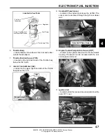
Страница 122: ...t between the throttle body and the cylinder head 3 Crankshaft Position Sensor CPS Located in the magneto cover between the engine and transmission just in front of the rear gear case 4 Fuel Injectors...

Страница 123: ...9 Camshaft Phase Sensor Located in the engine block above the oil filter The sensor can be accessed through the right rear wheel well 10 Engine Coolant Temperature Sensor ECT Located in the cylinder...

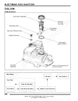
Страница 124: ...ER RZR RZR S RZR 4 Service Manual Copyright 2012 Polaris Sales Inc FUEL TANK Exploded View Fuel Flow Fuel Filters Fuel Pump Assembly Quick Connect Fuel Line Fuel Rail Fuel Injectors Pressure Regulator...

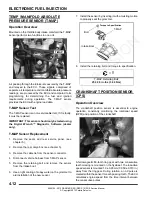
Страница 125: ...uel Squeeze the connector tabs together and push the locking slide back 2 Pull on the fuel line for removal 3 To install the line s verify the connections are clean and free of debris 4 Snap the fuel...

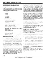
Страница 126: ...s The controlled injection of the fuel occurs every other crankshaft revolution or once for each 4 stroke cycle The total amount of fuel needed for one firing of a cylinder is injected during each cyc...

Страница 127: ...moment the battery cables are connected To prevent engine over speed and possible failure an RPM limiting feature is programmed into the ECU If the maximum RPM limit is exceeded the ECU suppresses th...

Страница 128: ...the rear cargo box see chapter 5 3 Remove the cable tie from the sensor connector 4 Disconnect vehicle harness from T MAP sensor 5 Remove the retaining bolt and remove the sensor from the intake boot...

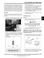
Страница 129: ...ector terminals and the corresponding pin terminals at the ECU see wiring diagram Check the sensor mounting air gap flywheel ring gear for damage or runout and flywheel key Follow the CPS Replacement...

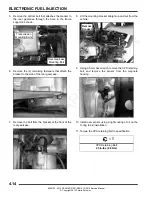
Страница 130: ...case 7 Remove the bolt from the bracket at the front of the rear gearcase 8 Lift the mounting bracket straight up and out from the vehicle 9 Using a 5 mm hex wrench remove the CPS retaining bolt and r...

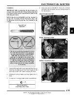
Страница 131: ...alling the bolts 2 Reinstall mounting bracket and hand tighten the 7 bolts 3 Torque ALL mounting bracket bolts to specification 4 Using special tool PA 48873 torque the 3 bolts that retain the front p...

Страница 132: ...per 2 bolts retaining the mounting bracket to the rear gearcase Place the torque wrench through the rear exhaust silencer opening to gain access to the bolts Middle Rear Gearcase Bolt Upper Rear Gearc...

Страница 133: ...ation indicating that they are opening and closing When temperatures prohibit touching listen for a buzzing or clicking sound with a screwdriver or mechanic s stethoscope Disconnect the electrical con...

Страница 134: ...r connectors for proper engine function PTO GRAY MAG BLACK Fuel Injector Replacement 1 Be sure the engine has cooled enough to work on 2 Remove seats and rear service panel see chapter 5 RZR RZR S Rem...

Страница 135: ...Thoroughly clean the area around the fuel injectors including the throttle body manifold 7 Using a 6 mm hex wrench loosen the fuel rail mounting screw from the cylinder head Carefully pull the rail a...

Страница 136: ...d to the start position If the engine fails to start If the engine is stopped with the key switch on as in the case of an accident In these situations the check engine light will turn on but turn off...

Страница 137: ...s out of specification replace the fuel pump assembly 6 If the pump did not activate Step 5 disconnect the harness connector from the fuel pump Connect a DC voltmeter across terminals 3 and 4 in the p...

Страница 138: ...ool PU 50326 over the fuel pump PFA nut Using a 1 2 drive ratchet or breaker bar loosen and remove the PFA nut Discard the PFA nut NOTE Apply downward force on the fuel pump flange while removing the...

Страница 139: ...shlight and mirror If debris like mud or sand is present fuel tank should be flushed and cleaned out prior to installation of new fuel pump assembly IMPORTANT It is recommended to remove the fuel tank...

Страница 140: ...l aligned between fuel pump and fuel tank 17 Torque PFA nut to specification using the Fuel Pump Service Tool PU 50326 and a calibrated torque wrench 18 Verify alignment of fuel pump and tank orientat...

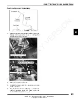
Страница 141: ...A small amount of fuel may come out of the fuel line or tank Properly drain fuel into a suitable container 4 Disconnect the fuel pump electrical harness 5 Remove fuel tank vent hose clamp with a suit...

Страница 142: ...well and remove the fender well from the vehicle see chapter 5 11 Remove the 3 shift lever support bracket bolts and place the bracket out of the way of the fuel tank but do not remove or cut the plas...

Страница 143: ...ully lift the rocker panel up over the fuel tank filler neck Reinstall fuel tank cap once rocker panel is removed 4 Remove the rocker panel from the vehicle 5 Remove the lower bolt retaining the seat...

Страница 144: ...for removal of fuel tank 9 Disconnect the fuel pump electrical harness 10 Remove fuel tank vent hose clamp with a suitable pliers and remove vent line from the tank vent fitting 11 While holding a sho...

Страница 145: ...all the rear RH panel divider and secure with fasteners RZR 4 5 Reinstall the seat belt mechanism and secure the lower bolt 6 Reinstall the RH rocker panel and all previously removed fasteners 7 Reins...

Страница 146: ...values at each of the following pin locations of the IAC If any of the readings are out of specification replace the IAC IAC Replacement 1 Remove the seats rear service panel and the rear cargo box s...

Страница 147: ...With the test leads connected and the meter set to the ohms scale observe the reading at the following pin locations of the TPS TPS Tester Regulator The TPS reading can be checked by using the Throttl...

Страница 148: ...obtain the proper voltage reading 1 Remove the seats rear service panel and the rear cargo box see Chapter 5 2 Loosen the hose clamps retaining the throttle body 3 Remove the throttle body from the in...

Страница 149: ...t up and testing Verify the 9 volt tester battery is new 2 Plug the TPS Tester harness into the new TPS 3 Set your voltmeter to read DC Volts Insert the red and black voltmeter probes into the test po...

Страница 150: ...ge present on the Red Dark Blue wire and ground present on the Brown wire NOTE Use Digital Wrench Diagnostic Software dealer only if you suspect this sensor is faulty Cam Phase Sensor Replacement 1 Ac...

Страница 151: ...rt the engine After a few seconds the fan should turn on and the Check Engine indicator should display on the instrument cluster This indicates all other components are working properly Refer to Chapt...

Страница 152: ...r and ignition coil post The engine will misfire if the spark plug wires are installed incorrectly The spark plug wires are marked with PTO and MAG from the factory and should be installed to the corr...

Страница 153: ...nformation area The first number located far left can range from 0 to 9 This number represents the total number of trouble code present example 2 means there are 3 codes present The second number loca...

Страница 154: ...Grounded 652 5 P0264 Driver Circuit Short to B 3 P0265 Driver Circuit Grounded 4 P1265 Rear Differential Output Driver Circuit Open Grounded 746 5 P1691 Driver Circuit Short to B 3 P1692 Driver Circui...

Страница 155: ...ror Software Error 520229 12 C1070 IC CAN Communication with EPS EPS Off Line EPS DM1 not seen 520230 31 U0131 Idle Air Control Valve IAC M17 IAC Stepper Pin 3 Driver Circuit Open Grounded 520268 5 P1...

Страница 156: ...engine runs rough misses poor performance bog engine loads up backfire Air intake restricted inspect intake duct Air filter dirty plugged Poor fuel quality old fuel Fouled spark plug TPS setting incor...

Страница 157: ...thin the original ECU is transferred to the replacement ECU Refer to procedure and carefully follow all instructions provided in Digital Wrench Guided Diagnostic Available Guided diagnostics are avail...

Страница 158: ...he lower left corner of the screen 5 Once connected proceed with using Digital Wrench Digital Wrench Serial Number Location Open the configuration screen by clicking on the wrench icon The serial numb...

Страница 159: ...Version Updates IMPORTANT You must already have the current version installed before adding an update Updates will not install if you are using an older version loaded on your PC 6 If the update file...

Страница 160: ...4 44 ELECTRONIC FUEL INJECTION 9924125 2013 RANGER RZR RZR S RZR 4 Service Manual Copyright 2012 Polaris Sales Inc Digital Wrench Feature Map P R E L I M I N A R Y V E R S I O N...

Страница 161: ...is more likely to cause a reprogramming problem than one dedicated to Digital Wrench diagnostics only OBTAINING THE LATEST UPDATE Reprogramming updates are provided periodically and contain the most r...

Страница 162: ...Reprogramming 7 Select the file you want to load into the ECU then click the Continue icon to proceed to the Integrity Check and obtain a Request Code 8 Copy CTRL C the Request Code that will be requ...

Страница 163: ...in the upper left corner of the screen Copy CTRL C this key exactly as it appears 13 Enter or paste CTRL C the Authorization Key in the box located on the Digital Wrench screen Click the Continue but...

Страница 164: ...NOTES ELECTRONIC FUEL INJECTION 4 48 9924125 2013 RANGER RZR RZR S RZR 4 Service Manual Copyright 2012 Polaris Sales Inc P R E L I M I N A R Y V E R S I O N...

Страница 165: ...OVER RZR 4 5 20 FRONT BUMPER 5 20 REAR BUMPER 5 21 HOOD AND FRONT BODY WORK 5 21 REAR FENDER FLAIR AND TIE DOWN REMOVAL 5 22 CARGO BOX ASSEMBLY REMOVAL 5 23 ROCKER PANELS CONSOLE AND FLOOR 5 23 STEERI...

Страница 166: ...ZR S 5 48 FOX 1 5 PODIUM PIGGYBACK GENERAL SERVICE INFORMATION 5 49 FRONT SHOCK SERVICE RZR S 5 49 REAR SHOCK SERVICE RZR S 5 49 FOX 2 0 PODIUM PIGGYBACK SHOCK RZR 4 L E MODELS 5 50 FOX 2 0 PODIUM PIG...

Страница 167: ...eel Hub Castle Nuts 80 ft lbs 108 Nm Wheel Nuts Cast Rims 30 ft lbs 41 Nm 90 Wheel Nuts Steel Rims 27 ft lbs 37 Nm Tie Rod End Jam Nut 13 ft lbs 18 Nm Seat Belt to Seat Base 40 ft lbs 54 Nm Tilt Shock...

Страница 168: ...M10x1 5x25 bolts and M10x1 5 nuts Tighten bolts to specification Fasten the two self tapping screws to the rear inner portion of the bracket on each side Tighten screws to specification 3 Place the s...

Страница 169: ...5 5 BODY STEERING SUSPENSION 5 9924125 2013 RANGER RZR RZR S RZR 4 Service Manual Copyright 2012 Polaris Sales Inc P R E L I M I N A R Y V E R S I O N...

Страница 170: ...en the front of the cab frame to the base brackets and mid cab frame using the 3 8 16 x 1 1 4 bolts and 3 8 16 Nyloc nuts Tighten bolts to 25 28 ft lbs 34 38 Nm 4 Fasten mid cab frame brackets to the...

Страница 171: ...5 7 BODY STEERING SUSPENSION 5 9924125 2013 RANGER RZR RZR S RZR 4 Service Manual Copyright 2012 Polaris Sales Inc P R E L I M I N A R Y V E R S I O N...

Страница 172: ...5 8 BODY STEERING SUSPENSION 9924125 2013 RANGER RZR RZR S RZR 4 Service Manual Copyright 2012 Polaris Sales Inc BODY EXPLODED VIEWS Side Safety Nets P R E L I M I N A R Y V E R S I O N...

Страница 173: ...ht 2012 Polaris Sales Inc Dash Instruments Controls Glovebox A Instrument Cluster Speedo B Headlight Switch C AWD 2WD or AWD 2WD TURF Switch D 12 Volt Accessory Receptacle E Key Switch F Hazard Switch...

Страница 174: ...laris Sales Inc Hood Front Body Work Center Access Hood Hood Dash Front Bumper Front RH Fender Flair Front LH Fender Flair Winch Pocket Cover Push Rivets Push Rivets T27 Screws 1 4 Turn Latch Grommet...

Страница 175: ...ENSION 5 9924125 2013 RANGER RZR RZR S RZR 4 Service Manual Copyright 2012 Polaris Sales Inc Rear Bumper RH Tail Light Rear Bumper Speed T25 Screws T27 Screws T27 Screw LH Tail Light Nuts P R E L I M...

Страница 176: ...p Plate Spring Lever Latch Body Grommets Seat Seat Back Seat Bottom Hoop Tube Nuts 41 57 in lbs 4 6 6 4 Nm 48 in lbs 5 4 Nm 41 57 in lbs 4 6 6 4 Nm Driver 3 Point Seat Belt Rear Seat Base Latch Seat P...

Страница 177: ...R 4 Latch 3 Point Seat Belts Plunger 40 ft lbs 54 Nm Front Seats 3 Point Seat Belts 40 ft lbs 54 Nm 40 ft lbs 54 Nm Front Seat Base Rear Seat Base Rear Seat Support Rubber Bumpers 40 ft lbs 54 Nm 40 f...

Страница 178: ...ver LH Rocker Lower Floor Rear Front Push Rivets U Type Support Bracket Rear Support Bracket Push Rivets Support Bracket Front Support Bracket Self Tapping Screws Self Tapping Screw T27 Screws T27 Scr...

Страница 179: ...Lower Floor Rear Front Push Rivets U Type Support Bracket Rear Support Bracket Support Bracket Torx Self Tapping Screws Self Tapping Screw Nuts Self Tapping Screw Upper Floor T27 Screw Front Support B...

Страница 180: ...Fender Rear LH Fender Cargo Box Tie Down Bracket Panel Divider Rear RH Panel Divider Rear Main Service Panel Supports Heat Shield Grommet Push Rivets Rivets T27 Tie Down Bracket Torx Screw Bolts T25...

Страница 181: ...sh Fender Flair Rear LH Fender Flair Fender Rear LH Fender Cargo Box Tie Down Bracket Floor Rear RH Floor Rear Console Cover Supports Heat Shield Grommet Rivet T27 Tie Down Bracket Torx Screw Bolts T2...

Страница 182: ...RZR S RZR 4 Service Manual Copyright 2012 Polaris Sales Inc Chassis Main Frame RZR RZR S Main Frame Bolt In Brace Skid Plate Rear Bumper Support 15 ft lbs 20 Nm 15 ft lbs 20 Nm 17 ft lbs 23 Nm 6 8 ft...

Страница 183: ...Main Frame RZR 4 Main Frame Bolt In Brace Rear Rear Bumper Support 15 ft lbs 20 Nm 15 ft lbs 20 Nm 17 ft lbs 23 Nm 6 8 ft lbs 8 11 Nm Front Frame Washers Self Tapping Screws Nylok Nuts Plug 38 ft lbs...

Страница 184: ...upward and towards the front of the vehicle to remove it Rear Console Cover RZR 4 1 Remove the rear passenger seats 2 Turn both latches 1 4 turn to disengage the cover 3 Pull out on the top while pre...

Страница 185: ...r portion of the hood 2 Tilt the hood back to disengage the front tabs and remove the hood from the vehicle Front Body Dash Removal 1 Remove the hood as previously described 2 Remove the front bumper...

Страница 186: ...assembly Rear Fender Flair and Tie Down Removal 1 Remove the rear bumper see BODY COMPONENT REMOVAL Rear Bumper 2 Remove the push rivets that retain the rear portion of the rocker panels to the rear f...

Страница 187: ...the chassis harness located above the airbox and remove the cargo box assembly from the vehicle Rocker Panels Console and Floor Rocker Panel Removal 1 Remove the push rivets and Torx screws retaining...

Страница 188: ...ect the battery and remove it from the vehicle 5 Remove the 8 fasteners that retain the lower portion of the mid cab frame to the main frame 6 Remove the 2 fasteners that retain the side bars to the m...

Страница 189: ...Cap Pivot Tube Steering Shaft Cotter Pin Gear Box Bearing Bushing Oil Locking Shock Asm Asm 17 ft lbs 23 Nm 17 ft lbs 23 Nm 12 14 ft lbs 16 19 Nm Nut 42 5 ft lbs 58 Nm 42 5 ft lbs 58 Nm 12 14 ft lbs...

Страница 190: ...the steering wheel off the shaft Steering Shaft Removal Non EPS Models 1 Remove the pinch bolt retaining the lower portion of the steering shaft to the steering gear box assembly 2 Remove the fastener...

Страница 191: ...by hand NOTE Use care not to allow any of the Loctite to get in the bearing NOTE Bearings will be seated in the pivot housing upon tightening the steering wheel nut in step 14 9 Reinstall the upper w...

Страница 192: ...lbs 27 33 Nm Boot Rod End Tie Rod RH Boot LH Boot Spacer Bearing Steering Cap Pivot Tube Cotter Pin Gear Box Bearing Oil Locking Shock Asm Asm 17 ft lbs 23 Nm 17 ft lbs 23 Nm 12 14 ft lbs 16 19 Nm 42...

Страница 193: ...shaft to the power steering unit 3 Remove the fastener retaining the upper portion of the steering wheel tilt shock to the pivot tube Swing the shock down out of the way 4 Lift the steering wheel up a...

Страница 194: ...ng wheel off the shaft taper 6 Once the steering wheel pops loose completely remove the nut and lift the steering wheel off the shaft Power Steering Unit Removal 1 Remove the upper steering shaft pivo...

Страница 195: ...e 4 bolts that retain the power steering unit to the mount bracket Lower Steering Shaft Removal EPS Models 1 Use the steering wheel to position the front wheels so they point straight ahead 2 Locate t...

Страница 196: ...stallation 1 If the power steering unit was removed from the mount bracket reinstall it prior to vehicle installation Torque the mounting bolts to specification 2 Remove the throttle pedal return spri...

Страница 197: ...ation 3 Install tilt shock and torque fastener to specification 4 Be sure the front wheels are pointing straight ahead and install the steering wheel and retaining nut Torque the nut to specification...

Страница 198: ...ck to A arm with spacer D or washer G and fastener A Torque lower shock bolt to specification 14 Remove lower ball joint pinch bolt E from bearing carrier 15 Using a soft face hammer tap on bearing ca...

Страница 199: ...m Grease Screws Ball Joint Pinch Bearing CV Shield Bushings Pivot Tube Bushing Grease Zerk Ball Joint Carrier Bolts Zerk Pivot Tube Upper Fastener Lower Fastener Upper A arm Lower A arm Grease Screws...

Страница 200: ...essary remove the lower front shock fastener from the A arm to gain enough clearance to install ball joint tool PU 50506 on the upper ball joint 4 To service the lower ball joint Remove and discard th...

Страница 201: ...itional A arm ball joint replacements 8 Insert upper lower A arm ball joint end into the bearing carrier Install new pinch bolts and nuts Torque to specification 9 If needed install new brake caliper...

Страница 202: ...steners to specification see Exploded View Stabilizer Bar Removal 1 If stabilizer bar linkages are installed RZR Remove the nut and linkage bushings see Exploded View RZR S INT L Remove the bolts that...

Страница 203: ...nt bracket and remove the bracket from the frame 9 Lift up on the stabilizer bar and remove it from the vehicle 10 Inspect the stabilizer bar for straightness Inspect the bushings and replace if neede...

Страница 204: ...tabilizer Bushings Grease Linkage Nuts Spacer Bracket Clamp 30 ft lbs Bar Bushings Bracket Mounts 37 ft lbs Linkage Washer Linkage Linkage 41 Nm 17 ft lbs 23 Nm Clamp 30 ft lbs Zerk Grease Zerk Nuts T...

Страница 205: ...e 3 Examine bushings and pivot tubes see Exploded View on page 5 40 Replace if worn Discard hardware 4 If not replacing the A arm thoroughly clean the a arm and pivot tubes 5 Insert new bushings and p...

Страница 206: ...and pivot tubes into new A arm Installation 1 Install lower A arm assembly onto vehicle frame Torque new fasteners to specification 2 Attach lower A arm to bearing carrier Torque new fastener to spec...

Страница 207: ...CV Bushings Pivot Tube Carrier Pivot Grease Zerk Shield Tube Bushings Pivot Tube Pivot Tube Bushings Upper Fastener Lower Fastener Lower Fastener Upper Fastener Upper A arm Lower A arm Screws Bearing...

Страница 208: ...ch side of the vehicle 3 Remove the 4 fasteners retaining the stabilizer bar bracket to the frame 4 Remove the stabilizer bar and bracket from the frame as an assembly 5 Inspect the stabilizer bar for...

Страница 209: ...lizer bar to the linkage on each side of the vehicle 3 Remove the 4 fasteners retaining the stabilizer bar to the bracket 4 Remove the stabilizer bar from the bracket bracket can remain attached to th...

Страница 210: ...nches from the flame tip is recommended Keep the torch moving to prevent damage 2 Apply the decal on one edge first Slowly lay down remainder of the decal while rubbing lightly over the decal surface...

Страница 211: ...efer to exploded views Shock Replacement 1 Using a spring compressor compress the shock spring far enough to remove the spring retainer 2 Remove the spring and adjusting cam from the existing shock an...

Страница 212: ...Nut 4 1 Reservoir 18 1 Bearing External 5 Shock Oil 2870995 19 1 Bearing External 6 1 Decal 20 2 Retaining Ring Wire 7 2 Bearing Spherical 21 1 Spring Guide 8 4 Retaining Ring 22 1 Piston Damping 9 1...

Страница 213: ...RESSION REBOUND 1 300 x 0 008 1 250 x 0 006 1 300 x 0 008 1 250 x 0 006 0 800 x 0 004 1 250 x 0 008 1 250 x 0 008 1 100 x 0 006 1 100 x 0 006 1 000 x 0 006 1 000 x 0 006 0 900 x 0 008 0 900 x 0 010 0...

Страница 214: ...dy 14 1 Preload Ring 4 1 Eyelet 15 1 Damping Adjust Asm Piston 5 1 Shaft 16 1 Damping Adjust Asm Concentric 6 1 Bearing Cap Asm 17 2 Bearing External 7 1 Bearing Asm 18 1 Bumper 8 1 Valving Asm 19 2 B...

Страница 215: ...00 x 0 010 1 425 x 0 008 1 600 x 0 006 1 425 x 0 008 1 425 x 0 010 1 425 x 0 008 1 350 x 0 010 1 425 x 0 008 1 250 x 0 012 1 425 x 0 008 1 100 x 0 012 1 100 x 0 004 0 950 x 0 012 1 425 x 0 012 0 800 x...

Страница 216: ...ng tool PS 45281 A to properly secure the shock body assembly into a vice for service 5 Remove the nylon ball from the reservoir cap using a heavy duty pick Discard nylon ball and replace with new upo...

Страница 217: ...rd on the IFP tool while pulling upward on the shock shaft to remove the shock shaft assembly 16 Remove the center screw and O ring from the IFP 17 Remove the IFP using the Shock IFP Tool 2871351 18 R...

Страница 218: ...s and let dry for reassembly 6 Remove the low speed compression cap using a 10 Torx bit driver 7 Use a 5 8 socket to remove the LSC DSC compression control 8 Replace the O rings on the low speed compr...

Страница 219: ...ock asm Bearing Cap 1 Use a small pick to remove seal from the bearing cap 2 Lubricate a new seal and fully install into bearing cap 3 Push the Shock Seal Protector Sleeve PU 50939 through the bearing...

Страница 220: ...bumper onto the shock rod 3 Install the Shock Seal Protector Sleeve PU 50939 onto the shaft threads 4 Lubricate the shock rod and the Shock Seal Protector Sleeve with new shock oil WARNING FOX shocks...

Страница 221: ...rod assembly from the vise and place on a clean shop towel 13 Use the appropriate shock body holding tool PS 45281 A to properly secure the shock body assembly into a vice for service 14 Fill the rese...

Страница 222: ...the oil 28 Add shock oil to 1 8 3 18 mm below the top of the shock body 29 Wrap a clean shop towel around top of shock body and depress the bearing assembly downward below the retaining ring groove 30...

Страница 223: ...nded pressure 46 Stroke the shock through its travel and adjust the external adjusters to ensure they are functioning properly 47 Use a rubber mallet to fully seat the bearing cap into position 48 Use...

Страница 224: ...Cap Asm 12 1 Preload Ring 2 1 Air Valve Asm 13 1 Retaining Ring 3 1 Body 14 1 Bumper 4 1 Shaft 620 O D 15 2 Spherical Bearing 5 1 Eyelet 16 1 Spiral Retaining Ring 6 1 Bearing Cap Asm Shock Oil 287099...

Страница 225: ...2 1 425 x 0 008 1 350 x 0 012 1 425 x 0 008 1 250 x 0 012 1 425 x 0 008 1 100 x 0 012 1 100 x 0 004 0 950 x 0 015 1 425 x 0 012 0 850 x 0 012 1 350 x 0 012 1 570 x 0 128 Top Out 1 250 x 0 015 1 100 x...

Страница 226: ...ith compressed air if available or use clean towels 5 Locate the retaining rings holding the spheical bearing in the ear of the body cap assembly 6 Use a small pick or flat blade screw driver to remov...

Страница 227: ...aft assembly out of the shock body 13 Remove the shock from the vise and pour shock oil into a proper disposal container DO NOT RE USE OIL SHOCK OIL 14 Mount the shock body using body clamp tools in t...

Страница 228: ...ntation of the rebound and compression sides of the piston 23 Remove the compression valve stack Fig 10 Zip tie the valves together Note that the valve shim closest to the piston is ported This is the...

Страница 229: ...dry Place clean parts on a lint free towel shop rag FOX 2 0 PODIUM Top Fill Reassembly NOTE Lubricate all seals o rings and wear bands with low temperature grease during assembly procedure 1 If the sh...

Страница 230: ...shaft NOTE The last compression valve shim is the air bleed shim The shim must be orientated correctly with the piston valve to allow air to bleed through the assembly during installation 10 Replace...

Страница 231: ...the piston valve when tightening lock nut 13 Replace the IFP o ring Apply a thin layer of low temerpature grease to the IFP 14 Install the IFP into the shock body with the relief contour facing the sh...

Страница 232: ...st the shock shaft valve stack Fig 24 23 Install the valve stack piston and bearing as an assembly into the shock body slowly Allow air bubles to escape the valve stack piston drop into the oil Fig 25...

Страница 233: ...twards 28 Inspect both ends of the shock assembly for leaks 29 Slide the shock body cap down to the body Use a soft faced hammer to drive the cap into the shock body Fig 28 30 Install the body cap and...

Страница 234: ...NOTES BODY STEERING SUSPENSION 5 70 9924125 2013 RANGER RZR RZR S RZR 4 Service Manual Copyright 2012 Polaris Sales Inc P R E L I M I N A R Y V E R S I O N...

Страница 235: ...ON EBS 6 10 BELT REMOVAL INSPECTION INSTALLATION 6 10 DRIVE BELT EBS 6 11 BELT REMOVAL INSPECTION INSTALLATION 6 11 DRIVE CLUTCH SERVICE 6 12 EXPLODED VIEW 6 12 SHIFT WEIGHTS 6 12 CLUTCH DISASSEMBLY 6...

Страница 236: ...ench PA 48595 Drive Clutch Puller Short 2870341 Drive Clutch Spider Removal and Installation Tool 2870386 Piston Pin Puller 2870910 Roller Pin Tool PU 50518 Universal Clutch Compressor PART NUMBER SPE...

Страница 237: ...gine RPM At full throttle a perfectly matched PVT system should hold engine RPM at the peak of the power curve This RPM should be maintained during clutch upshift and backshift In this respect the PVT...

Страница 238: ...ambient temperatures Warm engine at least 5 min then with transmission in neutral advance throttle to approx 1 8 throttle in short bursts 5 to 7 times The belt will become more flexible and prevent b...

Страница 239: ...Polaris Sales Inc PVT SYSTEM SERVICE PVT Covers and Ducting Components Inner Clutch Clamps Outer Cover Outer Push Rivets Outlet Duct Clutch Inlet Duct Screws Clutch Cover Clutch Cover Retainer Screws...

Страница 240: ...al RZR RZR S Remove the 2 fasteners from the rear seat base as shown and remove it from the vehicle RZR 4 Remove the 2 fasteners and seat latch plunger A RZR 4 Slide rear seat base towards left side o...

Страница 241: ...t be clean to ensure adhesion of silicone sealant 4 Install and properly align the inner clutch cover 5 Install the bolts and washers that retain the cover to the transmission Torque bolts to specific...

Страница 242: ...et adjustment is required Washers located behind the driven clutch on the transmission input shaft may need to be added or removed in order to obtain the proper offset Refer to the Clutch Offset Proce...

Страница 243: ...lutch cover and torque the cover screws to specification 8 Install the clutch cover outlet duct and tighten the clamps 9 Sit in the driver s seat apply the brake and start the engine Place the gear se...

Страница 244: ...es not move and the drive clutch engages the belt 2 Inspect belt for loose cords missing cogs cracks abrasions thin spots or excessive wear Compare belt measurements with a new drive belt Replace if n...

Страница 245: ...glassing occurs when the drive train does not move and the drive clutch engages the belt 2 Inspect belt for loose cords missing cogs cracks abrasions thin spots or excessive wear Compare belt measure...

Страница 246: ...shifting patterns Shift weights should not be changed or altered without first having a thorough understanding of their positioning and the effects they may have on belt to sheave clearance clutch ba...

Страница 247: ...here bushing rides for wear galling nicks or scratches Replace clutch assembly if worn or damaged 6 Remove and inspect the clutch spring Refer to Drive Clutch Spring Inspection Bearing Inspection 1 Ro...

Страница 248: ...s Inspect the contact surface of the weight The surface should be smooth and free of dents or gall marks Inspect the weight pivot bore and bolts for wear or galling If weights or bolts are worn or bro...

Страница 249: ...ounterclockwise using Clutch Spider Removal Tool PN 2870341 NOTE To maintain proper clutch balance and belt to sheave clearance be sure to reinstall the original quantity and thickness of washers spac...

Страница 250: ...pins Take care not to damage roller bushing or bearing surface of the new pin during installation 2 Rubber backed buttons can be used in all RANGER clutches if the hollow roller pin is changed to the...

Страница 251: ...worn or damaged Moveable Sheave Bushing Inspection Inspect the Teflon coating arrow on the moveable sheave bushing Inspect both sheaves for signs of wear grooving or cracking De glaze sheave surfaces...

Страница 252: ...tool Item A B into center of sheave with A side toward sheave EBS Clutch Bushing Tool Kit 2201379 Item Qty Part Tool Description A B 1 5132027 EBS Puller Tool C 1 5132501 EBS Puller Nut D 1 5132029 EB...

Страница 253: ...eated 8 Remove nut from puller rod and set aside 9 Remove sheave from puller 10 Remove installation tool Cover Bushing Removal 1 Install main adapter Item 8 on puller 2 Install adapter reducer Item 9...

Страница 254: ...der aligns with X or the marks that were made earlier on the moveable sheave 4 Torque spider to specification using the holding fixture and spider tool Torque with smooth motion to avoid damage to the...

Страница 255: ...niversal Clutch Compressor PU 50518 Apply and hold downward pressure on the outer spring retainer Carefully remove the snap ring Remember the outer spring retainer contains strong spring pressure NOTE...

Страница 256: ...D and inner spring retainer E 5 Separate the two clutch sheaves 6 Inspect the helix on the moveable sheave 7 Inspect the inner spring retainer for wear and replace as needed 8 Check the rollers in th...

Страница 257: ...a light film of grease Do not lubricate the bearings Clutch Assembly 1 Install the inner spring retainer if removed Do not apply oil or grease to the bearings 2 Align the X marks on each of the sheav...

Страница 258: ...Polaris Sales Inc 5 Install the outer retainer on top of the spring 6 Place the driven clutch into the Universal Clutch Compressor PU 50518 7 Apply and hold downward pressure on the outer spring retai...

Страница 259: ...n of the shaft cam cover and sheave before disassembly or use the X s on the components for reference This will aid in reassembly and helps to maintain clutch balance after reassembly 3 Remove the fou...

Страница 260: ...r E Inspect the spider dampener E for wear and replace if needed 8 Remove the E clips F washers G and the clutch rollers H Inspect the rollers for wear replace if worn 9 Remove the clutch assembly fro...

Страница 261: ...shings it will be necessary to apply heat evenly to the area around each bushing Clean all residual Loctite from bushing bore prior to installing new bushing Inspect Bushing Inspect Sheave Surface EBS...

Страница 262: ...free 8 Remove nut C left hand thread from puller rod and set aside 9 Remove adapters from puller 10 Remove bushing and removal tool from adapters Discard bushing Clutch Bushing Installation 1 Install...

Страница 263: ...a new snap ring 2 Install the shaft and bearing assembly into the outer sheave NOTE Press only on the outer race of the bearing during installation to prevent damaging the bearing 3 Line up the X on t...

Страница 264: ...each side of the outside spider Install the washers E and E clips F to secure the rollers The rollers should spin freely 9 Install the spider dampener G inside the outer spider and install the inside...

Страница 265: ...lix assembly over the shaft Line up the X on the cam X on spider and X on the stationary sheave or use the marks previously made before disassembly NOTE If the cam assembly helix is difficult to insta...

Страница 266: ...oded View Compression Thrust Washer Cam Helix Retaining Ring Roller Pin Slotted Ball E Clips Spring Spider Dampener Outer Spider Spider Insert Stationary Sheave Bearing Spring Pin Moveable Sheave Clut...

Страница 267: ...g range Incorrect drive clutch spring too high of rate Drive clutch shift weights incorrect for application too light Drive clutch binding Driven clutch binding Converter sheaves greasy belt slipage I...

Страница 268: ...tlined in Owner s Safety and Maintenance Manual Water ingestion Cover seals or ducts leaking Operator error Find leak and repair as necessary Instruct operator on guidelines for operation in wet terra...

Страница 269: ...EXPLODED VIEW 7 16 ALL WHEEL DRIVE OPERATION 7 17 AWD DIAGNOSIS 7 18 GEARCASE REMOVAL DISASSEMBLY INSPECTION 7 19 GEARCASE ASSEMBLY 7 22 GEARCASE INSTALLATION 7 24 REAR BEARING CARRIER 7 26 BEARING C...

Страница 270: ...ve the nut and 2 cone washers from the front wheel hub assembly 5 Remove the fastener retaining the steering tie rod end to the front bearing carrier PART NUMBER TOOL DESCRIPTION 2872608 Roll Pin Remo...

Страница 271: ...d minimal wear the bearings must be inspected visually and by feel While rotating bearings by hand inspect for rough spots discoloration or corrosion The bearings should turn smoothly and quietly with...

Страница 272: ...sing clean of any excess compound and install the snap ring Bearing Carrier Installation 1 Install drive shaft axle through the backside of the bearing carrier 2 Install the upper and lower ball joint...

Страница 273: ...er pin holes 10 Install wheel and 4 wheel nuts Torque wheel nuts to specification 11 Rotate wheel and check for smooth operation Bend both ends of cotter pin around end of spindle in different directi...

Страница 274: ...CAUTION Do not hang the caliper by the brake line Use wire to hang caliper to prevent damage to the brake line 5 Remove the front wheel hub assembly 6 Remove the upper ball joint pinch bolt 7 Using a...

Страница 275: ...ft faced hammer or brass drift to separate the outer CV joint from the drive shaft NOTE If using a brass drift be sure to tap on the inner race of the joint only 4 Make sure the circlip remains on the...

Страница 276: ...a soft faced hammer or brass drift to separate the plunging joint from the drive shaft NOTE If using a brass drift be sure to tap on the inner race of the joint only 5 Make sure the circlip remains on...

Страница 277: ...surfaces and place the excess grease in the boot 18 Pull the boot over the joint and position the boot lips into the grooves on the joint housing and shaft Make sure the boot is not dimpled or collaps...

Страница 278: ...ecessary 3 Install drive shaft into the front bearing carrier 4 Install the upper ball joint end into the front bearing carrier 5 Install the upper pinch bolt and torque to specification 6 Apply greas...

Страница 279: ...o the propshaft roll pin 2 Remove the gear selector cap and the retaining screw Remove the shift handle from the lever 3 Remove the Torx screws retaining the center console to access the propshaft 4 S...

Страница 280: ...el can be removed to gain better access to the propshaft roll pin 2 Remove both front seats 3 Remove the gear selector cap 4 Remove the retaining screw and the gear selector handle 5 Remove the fasten...

Страница 281: ...ropshaft use a NEW roll pin Support Bearing Replacement RZR 4 1 Follow steps 1 8 of the Removal Installation RZR 4 procedure 2 Remove the bearing support upper and lower half and the retaining ring Lo...

Страница 282: ...of the propshaft onto the front gearcase and install a NEW roll pin 11 Reinstall the center console selector handle and front seats PROPSHAFT U JOINT SERVICE Disassembly 1 Remove internal or external...

Страница 283: ...o force bearing caps in 3 Using a suitable arbor fully seat the bearing cap in one side Continually check for free movement of bearing cross as bearing caps are assembled 4 Install snap ring to contai...

Страница 284: ...eform 2 6 Ball Bearing Double Row 1 24 H Clip Spring 20 7 Bushing 1 26 Nylon Spacer 2 8 Bushing 1 27 Torsion Spring Retainer 1 9 Oil Seal 2 28 Backlash Spacer 1 10 Oil Seal 1 29 Ring Gear Spacer 1 11...

Страница 285: ...nside the ring gear to an engagement position While in the engagement position the front drive will be in an over running condition not engaged until the rear wheels lose traction Once the rear wheels...

Страница 286: ...n Step 5 A wear band with an interrupted wear mark may indicate a warped plate which may cause intermittent operation 5 Check to make sure the coil is seated in the U shaped insert that is pressed int...

Страница 287: ...ove the harness from the retaining dart 5 Remove the vent line from the front gearcase 6 Remove the 4 bolts securing the front gearcase to frame 7 Remove the gearcase from the front LH wheel well area...

Страница 288: ...be removed 4 Remove and inspect the armature plate Refer to AWD Diagnosis for detailed inspection process 5 Remove the torsion spring retainer and torsion spring from the top of the ring gear 6 Remov...

Страница 289: ...he roll cage assembly and rollers from the clutch housing Use a shop towel to cover the housing in order to retain all the rollers NOTE Rollers are spring loaded Take care not to allow them to fall ou...

Страница 290: ...section replace all O rings seals and worn components 2 Install pinion shaft assembly and install internal snap ring NOTE If bearing replacement was required press new bearing onto the pinion shaft an...

Страница 291: ...etainer on top of the torsion spring 8 Check the action of the torsion spring by rotating in both directions to ensure the spring and retainer are installed properly 9 Be sure the armature plate tabs...

Страница 292: ...earcase housing Install the 7 cover plate screws and torque to specification Gearcase Installation 1 Install the gearcase back into the vehicle through the LH wheel well area between the upper and low...

Страница 293: ...efer to FRONT DRIVE SHAFT Drive Shaft Installation and install both front drive shafts into the gearcase 7 Add the proper lubricant to the front gearcase Refer to Chapter 2 for fluid fill and change i...

Страница 294: ...heel hub assembly 5 Remove the two brake caliper mounting bolts CAUTION Do not hang caliper by the brake line Use wire to hang caliper to prevent damage to brake line 6 Remove the rear wheel hub assem...

Страница 295: ...er if damaged Bearing Installation 5 Thoroughly clean the rear bearing carrier housing and the outer race on the new bearing Be sure that all oil residue has been removed from each surface 6 Support t...

Страница 296: ...Install rear wheel hub assembly cone washers and hand tighten the castle nut Install washers with domed side out 5 Install brake caliper mounting bolts and torque to 18 ft lbs 24 Nm T Upper Rear Beari...

Страница 297: ...ts and remove rear wheel 3 Remove the cotter pin and loosen the rear wheel hub castle nut Remove the nut and 2 cone washers from the rear wheel hub assembly 4 Remove the two brake caliper mounting bol...

Страница 298: ...E Take care when removing to prevent damaging the seal 9 Inspect axle splines and CV boots for any damage Outer CV Joint Boot Replacement 1 Use a side cutters to cut and discard the boot clamps 2 Remo...

Страница 299: ...ide the small boot clamp and boot small end first onto the drive shaft and position the boot in it s groove machined in the shaft 11 Install a NEW circlip on the end of the shaft 12 Grease the joint w...

Страница 300: ...the joint housing and shaft Make sure the boot is not dimpled or collapsed 18 Install and tighten the large clamp using the appropriate clamp tool 19 While pulling out on the CV shaft slide a straight...

Страница 301: ...PORTANT If the grease in the joint is obviously contaminated with water and or dirt the joint should be replaced 7 Thoroughly clean the joint with an appropriate solvent and dry the joint to prevent a...

Страница 302: ...is securely fastened to the shaft 17 Remove excess grease from plunging joint s external surfaces and place the excess grease in the boot 18 Pull the boot over the joint and position the boot lips in...

Страница 303: ...all the drive shaft Use a soft faced hammer to tap on the outboard end of the drive shaft if necessary NOTE Take care when installing the drive shaft to prevent damaging the seal 3 Slide the rear driv...

Страница 304: ...b nut to specification and install a NEW cotter pin Tighten nut slightly if necessary to align cotter pin holes 9 Install wheel and 4 wheel nuts Torque wheel nuts to specification T Upper Rear Bearing...

Страница 305: ...Only Remove the upper A arm bolts lower rear A arm bolts and suspension plate NOTE If accessory rear rack cab frame is installed remove the 4 bolts retaining it to the rear suspension plate see photo...

Страница 306: ...o be disassembled and replaced Pinion and ring gear shimming information is NOT provided The components are matched at the factory which requires special OEM tooling in order to properly assemble and...

Страница 307: ...s from each side of the gearcase housing 7 Remove the input shaft seal using a seal puller or other suitable method 8 Inspect the input shaft by rotating the assembly in the gearcase housing while che...

Страница 308: ...ew seals on each side of gearcase housing using a standard seal installer Apply a thin coat of case sealant 2871557 to gearcase mating surfaces upon cover installation 3 If removed install each axle s...

Страница 309: ...ng the transmission to rear gearcase mount bracket it is extremely important to torque all 7 fasteners to specification Refer to the Installation procedure listed on page 4 14 NOTE Special tool PA 488...

Страница 310: ...nt LH 1 14 Screw Flange Head 2 5 Mount Rear 1 15 Seal Oil 2 6 Nut Flanged 4 16 Screw Flange Head 4 7 Assembly Rear Housing RH 1 17 Screw 8 8 N A 1 18 Dowel 2 9 Assembly Tapered Roller Bearing 2 19 Plu...

Страница 311: ...r away from the engagement dogs that are attached to the differential gear assembly This unlocks the rear differential When Differential Lock is selected on the switch power is removed from the electr...

Страница 312: ...AFT on page 7 29 2 Remove the exhaust pipe and exhaust silencer to allow for gearcase removal 3 Remove upper A arm bolts lower rear A arm bolts and suspension plate NOTE If accessory rear rack cab fra...

Страница 313: ...ck further to disengage it 9 Remove the vent line and lift the rear gearcase upward and on its side to remove it from the vehicle Gearcase Disassembly IMPORTANT The pinion gear assembly is NOT intende...

Страница 314: ...rom the differential assembly Be sure to keep the shims together for reassembly 7 Remove the bearing from the lower portion of the differential assembly Inspect the bearing for smoothness and wear 8 R...

Страница 315: ...orn or broken teeth If damaged replace the gearcase assembly NOTE In the event damage to the gears pinion bearings or housing requires replacement the entire assembly must be replaced 13 Remove the di...

Страница 316: ...e lock pin assembly from the gearcase housing 18 Carefully remove the shift yoke assembly from the gearcase cover 19 Inspect the shift lever A shift lever spring B shift return springs C shift yoke D...

Страница 317: ...remove the differential cover 3 Remove the upper differential gear 4 Use a scribe to mark the ring gear and differential case Remove the 8 bolts that secure the ring gear to the differential and allo...

Страница 318: ...e differential gears and thrust washers and slide the cross pin into position with the hole side facing the hole in the differential case 4 Install a new roll pin 5 Install the upper differential gear...

Страница 319: ...able method 4 Apply a thin coat of case sealant PN 2871557 to the gearcase mating surfaces upon cover installation 5 Install a new pinion shaft seal using a standard seal installer or other suitable m...

Страница 320: ...g 10 Install the lock pin assembly and tighten 11 Install the differential assembly into the gearcase housing 12 Assemble the gearcase halves and install the bolts that secure the cover to the housing...

Страница 321: ...procedure listed on page 4 14 NOTE Special tool PA 48873 will be required to torque the mounting bracket fasteners when the transmission and rear gearcase are installed in the vehicle Refer to the In...

Страница 322: ...1 28 Bearing Tapered Roller 1 10 Bearing Ball 2 29 Screw Flange Head 10 11 Plug Drain 1 30 Case Diff Cover Half 1 12 Shim Kit 2 31 Thrust Washer Pinion 2 13 Gear Clutch 1 32 Gear Diff Pinion Mate 2 14...

Страница 323: ...aining Sealed Ball Bearing Bearing Front Tire Washers 27 ft lbs 37 Nm 80 ft lbs 108 Nm Ring Carrier Steel Front Rim Aluminum Wheel Nuts 30 ft lbs 90 1 4 turn Studs Wheel Nuts Rear Rim Castle Nut Cotte...

Страница 324: ...NOTES FINAL DRIVE 7 56 9924125 2013 RANGER RZR RZR S RZR 4 Service Manual Copyright 2012 Polaris Sales Inc P R E L I M I N A R Y V E R S I O N...

Страница 325: ...8 2 REMOVAL 8 2 INSTALLATION 8 2 SHIFT CABLE INSPECTION ADJUSTMENT 8 3 TRANSMISSION SERVICE 8 4 TRANSMISSION REMOVAL SERVICE NOTES 8 4 TRANSFER CASE DISASSEMBLY 8 4 TRANSFER CASE REASSEMBLY 8 7 TRANS...

Страница 326: ...o specification ITEM TORQUE VALUE Transmission Fill Plugs 40 50 ft lbs 54 67 Nm Transmission Drain Level Plugs 30 45 in lbs 0 2 0 3 Nm Transmission Case Screws 23 27 ft lbs 31 36 Nm Shift Cable Lever...

Страница 327: ...upper jam nut 4 Adjust the shift cable so there is the same amount of cable travel when shifting slightly past the detents of HIGH H gear and PARK P 5 Thread the upper or lower jam nut as required to...

Страница 328: ...e the transmission in the neutral position 2 Drain both the transfer case and transmission case halves 3 Remove the 7 fasteners retaining the transmission to rear gearcase mount bracket NOTE If replac...

Страница 329: ...and standard bearing removal tools Discard removed bearings as they become damaged by the removal process 10 Remove intermediate pinion shaft assembly from the housing Check bearings and gear teeth fo...

Страница 330: ...he shaft can be disassembled as shown using a press and standard bearing removal tools 14 Remove the upper snap ring from the top side of the 21T main pinion gear and remove the gear 15 Remove the low...

Страница 331: ...ring is pressed onto the shaft 3 Install the shims bearing cup and alignment dowels into the retaining bracket 4 Install a new output shaft seal flush with the case Install the output pinion shaft ass...

Страница 332: ...ue measurement from step 7 was below specification replace the existing shim s with a thicker shim or shim stack from the table below B If the rolling torque measurement from step 7 was above specific...

Страница 333: ...nents as required Press in new bearings and a seal using standard installation tools needle bearing is installed round edge inward Install a new shaft seal flush with the surface the shims and bearing...

Страница 334: ...ion replace the existing shim s with a thicker shim or shim stack from the table below B If the rolling torque measurement from step 22 was above specification remove or replace the existing shim s wi...

Страница 335: ...ification B If the torque required to rotate the output shaft is within specification no adjustment is needed and the transfer case reassembly is complete Transmission Shift Housing Disassembly IMPORT...

Страница 336: ...ning ring and retaining plate 4 Remove the reverse clutch gear assembly from the housing Inspect these components and replace if needed 5 Remove the 5 screws retaining the park flange Inspect the park...

Страница 337: ...to the shift housing Inspect the O ring switch poles and contact pins for wear or damage Replace parts as required 10 Remove the spacer contact pins springs drum gear and washer from the shift housin...

Страница 338: ...y from the shift collar as shown 16 Inspect the ball bearing channels on both ends of the shift collar for excessive wear or damage 17 Remove the sliding shoes from the clutch yoke 18 Remove the clutc...

Страница 339: ...ove the transmission input shaft from the housing Inspect the shaft bearing and replace if required using a shop press Inspect the gears for damage and or wear Replace the shaft if required 25 Remove...

Страница 340: ...tall the shift cable lever X facing out and torque the retaining screw to specification 3 Assemble the input shaft with new ball bearings if required NOTE Install new bearings and seals by pressing on...

Страница 341: ...ter groove of the shift collar Shifting the clutch shaft position may aid in shift collar installation 11 If removed install the detent sleeve assembly first Install the ball spring and outer detent s...

Страница 342: ...specification 13 Complete the shift detent screw installation Torque the outer detent screws to specification 14 Install reverse idler lower washer needle bearing gear upper washer and retaining ring...

Страница 343: ...low the case Apply lubricant to both seal lips 20 Place the transmission shift housing onto a flat surface as shown Apply a bead of crankcase sealant onto the mating surfaces Align the dowels and inst...

Страница 344: ...n rod ends Loose fasteners on selector box Worn rod ends clevis pins or pivot arm bushings Linkage rod adjustment and rod end positioning Shift selector rail travel Worn broken or damaged internal tra...

Страница 345: ...8 9924125 2013 RANGER RZR RZR S RZR 4 Service Manual Copyright 2012 Polaris Sales Inc TRANSMISSION EXPLODED VIEW Shift Housing Transfer Case Exploded View Transfer Case Shift Housing P R E L I M I N A...

Страница 346: ...NOTES TRANSMISSION 8 22 9924125 2013 RANGER RZR RZR S RZR 4 Service Manual Copyright 2012 Polaris Sales Inc P R E L I M I N A R Y V E R S I O N...

Страница 347: ...ICE 9 11 CALIPER EXPLODED VIEW RZR RZR S RZR S INT L 9 11 CALIPER EXPLODED VIEW RZR 4 9 11 CALIPER REMOVAL 9 12 CALIPER DISASSEMBLY 9 13 CALIPER INSPECTION 9 14 CALIPER ASSEMBLY 9 15 CALIPER INSTALLAT...

Страница 348: ...ervice Limit Rear Brake Pad Thickness 298 007 7 57 178 mm 180 4 6 mm Rear Brake Disc Thickness 188 4 78 mm 170 4 32 mm Rear Brake Disc Runout 010 254 mm Item Torque ft lbs Torque Nm Front Caliper Moun...

Страница 349: ...TROUBLESHOOTING Dirt or dust buildup on the brake pads and disc is the most common cause of brake noise squeal caused by vibration If cleaning does not reduce the occurrence of brake noise Permatex D...

Страница 350: ...elf adjusting Fluid from the reservoir fills the additional area created when the caliper piston moves outward Brake fluid level is critical to proper system operation Too little fluid will allow air...

Страница 351: ...nder LH Front Rear Calipers Brake Line LH Rear Line 1 2 1 1 2 2 1 3 All Flare Style Fittings 12 15 ft lbs 16 20 Nm 3 1 1 2 2 15 ft lbs 20 Nm 3 Fitting Switch Caliper Banjo Style Fittings 15 ft lbs 20...

Страница 352: ...ylinder to the frame Installation 1 Reverse Steps 1 5 for master cylinder installation Refer to the torque specifications in the illustration 2 After installing the foot brake check pedal freeplay Ped...

Страница 353: ...t release foot pedal before bleeder screw is tight or air may be drawn into master cylinder 7 Repeat procedure until clean fluid appears in bleeder hose and all air has been purged Add fluid as necess...

Страница 354: ...king or bending brake line 5 Push caliper piston into caliper bore slowly using a C clamp or locking pliers with pads installed NOTE Brake fluid will be forced through compensating port into master cy...

Страница 355: ...make sure dust boots are fully seated Install pads with friction material facing each other 3 Install caliper onto front hub and torque mounting bolts to specification Front Brake Pad Thickness RZR RZ...

Страница 356: ...ap 7 Install wheel and torque wheel nuts to specification Brake Burnishing Procedure It is required that a burnishing procedure be performed after installation of new brake pads to extend service life...

Страница 357: ...O ring thick F Square O ring thin G Piston H Caliper Mount I Brake Pads A B C D E F G H Apply Silicone Grease Apply Polaris DOT 4 Brake Fluid to Component I 47 in lbs 5 3 Nm D A B C D 47 in lbs 5 3 N...

Страница 358: ...iper to catch brake fluid when removing the line Remove brake line from caliper 5 Loosen brake pad adjustment set screw 2 3 turns to allow brake pad removal after the caliper is removed 6 Remove the t...

Страница 359: ...on pliers to extract the pistons from the caliper IMPORTANT Do not remove the caliper pistons with a standard pliers The piston sealing surfaces will become damaged if a standard pliers is used 5 Once...

Страница 360: ...sure piston diameter and replace if damaged or worn beyond service limit 3 Inspect the brake disc and pads as outlined in this chapter In mm RZR RZR S Front Caliper Piston Bore I D Std 1 004 25 5 mm S...

Страница 361: ...and make sure the dust seal boots are fully seated Install the brake pads Clean the disc and pads with brake parts cleaner or denatured alcohol to remove any dirt oil or grease Caliper Installation 1...

Страница 362: ...embly and installation NOTE If new pads are installed refer to FRONT BRAKE PADS Brake Burnishing Procedure FRONT BRAKE DISC Disc Runout 1 Mount dial indicator as shown Slowly rotate the disc and read...

Страница 363: ...a new cotter pin 7 Install the front brake caliper see FRONT CALIPER SERVICE 8 Follow bleeding procedure outlined earlier in this chapter 9 Field test unit for proper braking action before putting int...

Страница 364: ...to kink or bend brake line 5 Push caliper piston into the caliper bore slowly using a C clamp or locking pliers with pads installed NOTE Brake fluid will be forced through compensating port into maste...

Страница 365: ...uid level in reservoir is up to the MAX line inside reservoir and install reservoir cap 7 Install wheel and torque wheel nuts to specification Brake Burnishing Procedure It is required that a burnishi...

Страница 366: ...5 Loosen the brake pad adjustment set screw to allow brake pad removal after the caliper is removed 6 Remove the two caliper mounting bolts and remove the caliper A B C D E F G H I K Apply Polaris DOT...

Страница 367: ...ton and retaining bracket with brake cleaner or alcohol NOTE Be sure to clean seal grooves in caliper body Caliper Inspection 1 Inspect caliper body for nicks scratches or wear Measure bore size and c...

Страница 368: ...3 Lubricate the mounting bracket pins with silicone grease and install the rubber dust seal boots 4 Compress the mounting bracket and make sure the dust seals are fully seated Install the brake pads...

Страница 369: ...d turn until stationary pad contacts disc then back off 1 2 turn 4 Follow bleeding procedure outlined earlier in this chapter 5 Install wheel and torque wheel nuts to specification NOTE If new pads ar...

Страница 370: ...ake caliper see REAR CALIPER SERVICE 2 Remove wheel hub cotter pin castle nut and washers 3 Remove the hub assembly from the vehicle and remove the 4 bolts retaining the disc to the hub 4 Clean the wh...

Страница 371: ...r in system Water in system brake fluid contaminated Caliper or disc misaligned Caliper dirty or damaged Brake line damaged or lining ruptured Worn disc and or friction pads Incorrectly adjusted stati...

Страница 372: ...NOTES BRAKES 9 26 9924125 2013 RANGER RZR RZR S RZR 4 Service Manual Copyright 2012 Polaris Sales Inc P R E L I M I N A R Y V E R S I O N...

Страница 373: ...PERATION OVERVIEW 10 11 DIAGNOSING SYSTEM FAILURES 10 11 INSTRUMENT CLUSTER 10 12 OVERVIEW 10 12 RIDER INFORMATION DISPLAY 10 13 INFORMATION DISPLAY AREA 10 13 DIAGNOSTIC MODE 10 16 INSTRUMENT CLUSTER...

Страница 374: ...ING 10 33 OCV OPEN CIRCUIT VOLTAGE TEST 10 33 LOAD TEST 10 33 BATTERY CONDUCTANCE ANALYZER 10 34 CHARGING PROCEDURE 10 34 STARTING SYSTEM 10 35 TROUBLESHOOTING 10 35 VOLTAGE DROP TEST 10 35 STARTER MO...

Страница 375: ...to the prefix on the multimeter reading K M etc and the position of the decimal point For resistance readings isolate the component to be tested Disconnect it from the wiring harness or power supply...

Страница 376: ...to LOW There should be continuity between switch pins 2 and 3 4 and 5 Move the switch to OFF There should be continuity between switch pins 1 and 2 4 and 5 NOTE Pins 7 and 8 provide power and ground t...

Страница 377: ...nuity between switch pins A E and F C and D Turn the ignition key to ON There should be continuity between pins C and D E and F Turn the ignition key to START There should be continuity between pins A...

Страница 378: ...switch pins 1 and 2 4 and 5 Turn Signal Switch INT L 1 Disconnect the Turn Signal switch harness by depressing the connector locks and pulling on the connector Do not pull on the wiring 2 Test betwee...

Страница 379: ...ect the transmission switch harness by lifting the connector lock and pulling on the connector Do not pull on the wiring 2 Test the transmission switch continuity readings for each gear position and c...

Страница 380: ...ocated in the drivers foot control area mounted on the top of the throttle pedal asm TRS Testing The TRS is a serviceable item and can be tested using Digital Wrench or an Ohm meter 1 Disconect the TR...

Страница 381: ...m and loosley install the 2 fastiners 2 The TRS mounting holes are oblonged to allow for switch alignment Visually center the TRS slot with the throttle pedal blade C It may be necessary to manually c...

Страница 382: ...ed on the rear gear case The solenoid actuates an engagement dog which locks and unlocks the rear differential Refer to Chapter 7 for more information on the mechanical operation Differential Solenoid...

Страница 383: ...the hub coil Verify the AWD hub coil is functional Test the AWD hub coil using an ohm meter See specifications below Verify the wiring harness wiring connectors connector pins and grounds are undamage...

Страница 384: ...ns NOTE Some features are not applicable to all models IMPORTANT The use of a high pressure washer may damage the instrument cluster Wash the vehicle by hand or with a garden hose using mild soap Cert...

Страница 385: ...and adjustable by the user a flashing wrench symbol alerts the operator that the preset service interval has been reached and maintenance should be performed The wrench icon will flash for 10 seconds...

Страница 386: ...hours can not be reset Programmed Service Interval The initial factory service interval setting is 50 hours Each time the engine is started the engine hours are subtracted from the service interval ho...

Страница 387: ...elease the button 5 Repeat steps 3 4 twice to set the 10 minute and 1 minute segments After completing the 1 minute segment step 4 will save the new settings and exit the clock mode Units of Measureme...

Страница 388: ...to display diagnostic trouble codes that were activated during current ignition cycle causing the MIL to illuminate Diagnostic trouble codes will remain stored in the gauge even if MIL turns off unti...

Страница 389: ...Only remove the rubber mount if necessary The bezel is a snap on assembly and is a serviceable part Instrument Cluster Installation 1 Spray a soap and water mixture onto outer surface area of instrum...

Страница 390: ...e 5 Adjust the beam to the desired position by loosening the adjustment screw A and moving the lamp to the appropriate height 6 Adjust the beam to desired position Repeat the procedure to adjust the o...

Страница 391: ...re insert bulb if previously removed 4 Adjust headlights using the Headlight Adjustment procedure in this section HEAD LIGHTS LED Headlight Adjustment The headlight beams are adjustable 1 Place the v...

Страница 392: ...gs onto the front bumper mounting bosses 2 Insert the 3 T 25 headlamp mounting screws into the headlamp assembly mounting holes 3 Maneuver headlamp assembly into position Be sure all 3 headlamp spring...

Страница 393: ...th is present If a tail light brake light or turn signal INT L Only does not work the bulb may need to be replaced 1 Disconnect the wire harness 2 Remove bulb by turning the rubber base 1 4 turn and p...

Страница 394: ...10 22 ELECTRICAL 9924125 2013 RANGER RZR RZR S RZR 4 Service Manual Copyright 2012 Polaris Sales Inc COOLING SYSTEM Cooling System Break Out Diagram...

Страница 395: ...sor can be tested using an ohmmeter or voltmeter 1 With the engine and temperature sensor at room temperature 68 F 20 C disconnect the harness 2 With the meter in the ohms mode place the meter leads o...

Страница 396: ...tection for wiring and components such as the instrument cluster ECU EFI system main harness lights accessories and power steering The relays assist with component operation like the cooling fan fuel...

Страница 397: ...24125 2013 RANGER RZR RZR S RZR 4 Service Manual Copyright 2012 Polaris Sales Inc Fuse Box Detail IMPORTANT All relays PN 4011283 located in fuse box are the same and can be swapped out to help diagno...

Страница 398: ...Vdc constant battery voltage Brown Relay coil ground Orange 12 Vdc power input from key switch to enable relay White Provides 12 Vdc power for lights drive and accessory circuits COLOR FUNCTION Red Wh...

Страница 399: ...lights Low Beam Headlights COLOR FUNCTION Red Dark Green 10 Amp fuse protected 12 Vdc battery voltage Dark Green White ECU input to enable relay Brown Relay coil ground Red Relay switched power to ope...

Страница 400: ...battery discharge 3 Shift transmission into park and start the engine With the engine running at idle observe meter readings 4 Increase engine RPM while observing ammeter and tachometer Note the RPM...

Страница 401: ...put of Each Stator Leg at Charging RPM 1 Set the selector dial to measure AC Voltage 2 Start the engine and let it idle 3 While holding the engine at a specified RPM separately measure the voltage acr...

Страница 402: ...ted behind the radiator cooling fan and can be accessed through the front left wheel well NOTE If the regulator rectifier overheats the unit will turn itself off to cool down The unit will turn on aga...

Страница 403: ...f operated below the Break Even RPM Con tinued problems would call for battery inspection Yes Inspect the wiring harness between the panel and the stator for remove the recoil and flywheel Inspect the...

Страница 404: ...TX20HL BS Sealed Maintenance Free Voltage 12 Vdc Nominal Capacity 10 HR Rate 18 AH CCA 310 Nominal Open Circuit Voltage 12 8 Vdc or more Recommended Charging Rate 1 8A 5 10 HR or 9 0A 1 HR Type Polari...

Страница 405: ...olts or less require further battery testing and charging See the following chart and Load Test NOTE Maintenance Free batteries should be kept at a high state of charge during storage If the battery i...

Страница 406: ...when charging is complete NOTE Allow the battery to stand disconnected for at least 1 2 hours after being properly charged If the voltage drops below 12 6 volts charging was ineffective or the battery...

Страница 407: ...otor gear Faulty flywheel gear or loose flywheel Voltage Drop Test The Voltage Drop Test is used to test for bad connections When performing the test you are testing the amount of voltage drop through...

Страница 408: ...t to specification 6 Install the negative battery cable to the lower mounting bolt Install battery cable nut and torque to specification 7 Install the positive battery cable to the starter motor 8 Ins...

Страница 409: ...W between terminals A and B If resistance measurement is out of specification replace the starter solenoid Starter Solenoid Operation To energize the Starter Solenoid the following must occur The brak...

Страница 410: ...ia the 2 wire connection With the solenoid energized resistance should read about 0 5 10 between the two terminals If resistance measurement is out of specification replace the starter solenoid see St...

Страница 411: ...g unit will operate for up to five minutes After the five minutes you will need to cycle the key switch and restart the engine to regain power steering operation The Power Steering 30A Fuse If the fus...

Страница 412: ...10 40 ELECTRICAL 9924125 2013 RANGER RZR RZR S RZR 4 Service Manual Copyright 2012 Polaris Sales Inc EPS System Breakout...

Страница 413: ...10 41 ELECTRICAL 10 9924125 2013 RANGER RZR RZR S RZR 4 Service Manual Copyright 2012 Polaris Sales Inc EPS Troubleshooting Power Steering Non Functional with MIL ON...

Страница 414: ...10 42 ELECTRICAL 9924125 2013 RANGER RZR RZR S RZR 4 Service Manual Copyright 2012 Polaris Sales Inc EPS Troubleshooting Power Steering Non Functional with MIL OFF...

Страница 415: ...NGER RZR RZR S RZR 4 Service Manual Copyright 2012 Polaris Sales Inc EPS Troubleshooting Using Digital Wrench These Error Codes must have multiple occurrences or you must be able to duplicate the cond...

Страница 416: ...NOTES ELECTRICAL 10 44 9924125 2013 RANGER RZR RZR S RZR 4 Service Manual Copyright 2012 Polaris Sales Inc...

Страница 417: ...2013 RANGER RZR 800...

Страница 418: ...2013 RANGER RZR 800...

Страница 419: ...2013 RANGER RZR 800 EPS...

Страница 420: ...2013 RANGER RZR 800 EPS...

Страница 421: ...2013 RANGER RZR S 800...

Страница 422: ...2013 RANGER RZR S 800...

Страница 423: ...2013 RANGER RZR S 800 INT L...

Страница 424: ...2013 RANGER RZR S 800 INT L...

Страница 425: ...2013 RANGER RZR 4 800...

Страница 426: ...2013 RANGER RZR 4 800...

Страница 427: ...2013 RANGER RZR 4 800 EPS...

Страница 428: ...2013 RANGER RZR 4 800 EPS...

Страница 429: ...2013 RANGER RZR RZR S RZR 4 CARGO BOX...

Страница 430: ...2013 RANGER RZR S 800 INT L CARGO BOX...

Отзывы: