Connecting to the Controller
MultiFlex PCI 1000 Series User's Manual
49
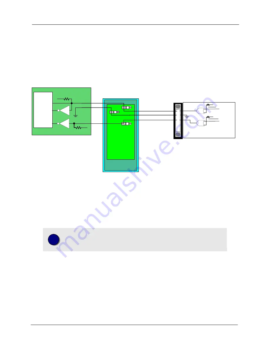
PWM (Pulse Width Modulation) Command Connections
Connectors J1 and J2 each provide two PWM command outputs for controlling the position of as many as
four PWM command servos. Each output is driven by an Open Collector Driver (75434) and is capable of
sinking as much as 100 mA (max. voltage = 30V ). The PWM Command outputs are available on pins 6
and 7 of connectors J1 & J2. Any of the Grounds signals can be used as a reference. The typical
interconnections for a Bipolar PWM servo are shown below.
PWM Command
Output
Ground
J1
6
57
Motion Controller
ADAM-3968
wiring module
6
57
75453
PWM Out
PWM Driver
ST Micro
L6203
In
1
In
2
+5V
4.7K
5
75453
Amp Enable
5
Enable
+5V
4.7K
Axis #1 Amp Enable
Figure 10. Bipolar PWM command wiring example (axis #1). The ST Micro L6203 is shown for
example purposes only - THIS INTERCONNECT DRAWING IS NOT INTENDED TO BE USED FOR
CIRCUIT DESIGN.
i
For information on configuring and operating a PWM servo please refer
to the
PWM Command Motion
description in the
Application
Solutions
chapter of this manual (page 147 .
Unipolar PWM
A unipolar PWM requires both a PWM Command (Magnitued) signal and a Direction (Sign) signal. Due to
I/O limits the controller does not provide a dedicated PWM Direction output, but any of the general
purpose Digital Outputs can be configured to this function. For information on configuring the Digital
Outputs please refer to page 165. The typical interconnections for a Unipolar PWM servo are shown
below.
Artisan Technology Group - Quality Instrumentation ... Guaranteed | (888) 88-SOURCE | www.artisantg.com


