


•
Oxygen measurement* with
measured or constant sensor
temperature
* Precise determination of O2 content by
means of Nernst equation.
Signal manipulation
Depending on the selected sensor
type, the following options are provi-
ded for manipulating the input signal:
•
Measurement value correction
(offset and 2-point)
•
Scaling
•
1st-order filter
•
Linearization with 15 segments
•
Substitute value in case of an error
Behaviour on sensor break/short circuit
•
Controller outputs disabled (off)
•
Output of a fixed safety value
•
Output of a calculated mean value
(PID controllers)
•
Preset substitute input value, can
be disabled
Display of engineering units
The engineering unit for the measured
value can either be selected from a
predefined list of standard units, or it
can be defined by the user (BlueCon-
trol
®
). The unit appears in the second
line of the display.
LIMIT VALUE FUNCTIONS
Max, Min or Max/Min monitoring with
adjustable hysteresis.
Monitored signals
•
Process value
•
Control deviation (with suppression
during start-up or setpoint changes)
•
Input 1, Input 2
•
Setpoint
•
Output value
Functions
•
Input value monitoring
•
Input value monitoring with storage,
and reset via front panel or digital input
•
Several limit values and alarm
messages can be logically
”OR-linked”.
Applications: Releasing a brake on
motor actuators, generating a
common alarm, etc.
•
Limit signals can be used as control
input.
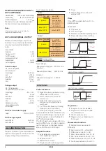
ALARMS
Heating current alarm
•
Overload & short circuit
•
Open circuit & short circuit
Limit:
adjustable, 0 … 9,999A
Open control loop
Automatic detection, if there is no re-
sponse from the process after a chan-
ge in output value.
Sensor break / short circuit
Depending on the selected input type,
the input circuit is monitored for break,
short circuit, and reversed polarity.
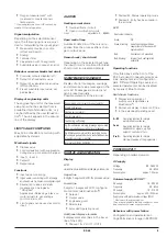
MAINTENANCE MANAGER
Display of error messages, warnings,
and stored limit value messages in the
error list. Messages are stored, and
can be reset manually.
Possible elements in the error list:
Sensor break, short circuit, incorrect polarity
Stored limit values
Heating current alarm
Control loop alarm
Fault during self-tuning
E.g. Re-calibration warning (message is generated
when a predefined operating time is reached)
E.g. Maintenance interval for a switching device
(message is generated when a predefined number
of switching cycles is reached)
Internal fault (RAM, EEPROM, ...)
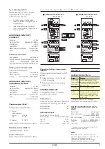
DISPLAY AND OPERATION
Display
LCD
dual-line plus additional display elements
Upper line
4 digits, 7-segment LCD for process value
Lower line
5 digits, 14-segment LCD; configura-
ble contents (via BlueControl
®
)
•
Setpoint
•
Output value
•
Engineering unit
•
Parameters
•
Extended Operating Level
Additional display elements
4 display elements (bars in the lower
line of the LCD)
•
Marked 1 & 2: OUT1 / OUT2
•
Marked M: Manual operating mode
•
Marked E: Entry has been made in
the error list
LED
Dual-colour indicator
Green:
OK
Green, blinking: no data exchange with bus
coupler (only for devices with
system option)
Red:
limit value Lim1 exceeded
Red, blinking:
internal fault, configuration
mismatch
Operating functions
Only three keys at the front of the
KS 45 are used to operate process va-
lues, parameters, and configuration
data. Different Operating Levels and
selected parameters can be disabled
by means of BlueControl
®
.
Switchover functions
•
Display and operation of
switchovers (adjustable via
BlueControl
®
)
•
Permanent display in lower LCD line
•
In the extended Operating Level
A-M
Operating function for simple
auto/manual switchover
Func
Operating function for simple
switchover of signals, e.g. 2nd
setpoint, controller off, etc.
ProG
Operating function for simple
starting/stopping of the programmer
POWER SUPPLY
Depending on ordered version:
AC supply
Voltage:
90...260 V AC
Frequency:
48...62 Hz
Consumption:
approx. 7 VA max.
Universal supply 24 V UC*
AC supply:
18...30 V AC
Frequency:
48...62 Hz
DC supply:
18...31 V DC
Consumption:
approx. 4 VA / 3W max.
Supply only with protective low voltage (SELV)
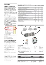
* Devices with system option:
They are supplied via the bus connector from
bus coupler or power supply module.
Behaviour with power failure
Configuration and parameter set-
tings:Permanent storage in EEPROM
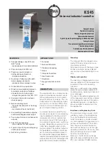
KS 45
5


