


OPTOCOUPLER OUTPUTS OUT1,
OUT2 (OPTIONAL)
Grounded load:
common ‘plus’ control voltage
Switch rating:
18...32 V DC; max. 70 mA
Internal voltage drop:
ß
1 V at I
max
Protective circuits: fitted as standard
for short circuit, reversed polarity.
Note:
A free-wheel diode has to be fitted for
inductive loads externally.
OUT3 AS UNIVERSAL OUTPUT
Parallel current/voltage output with
common ‘minus’ terminal (combined
use only in galvanically isolated cir-
cuits).
Freely scalable
Resolution:
14 bits
Tracking error I/U:
ß
2%
Cut-off frequency:
> 2 Hz
(continuous controller)
Residual ripple:
ß_
1%
(rel. to range end)
0...130kHz
Current output
0/4...20 mA, configurable,
short-circuit proof.
Control range:
-0.5...23 mA
Load:
ß
700
Ω
Load effect:
ß
0.02%
Resolution:
ß
1.5 µA
Error:
ß
0.1%
Voltage output
0/2...10V, configurable,
not permanently short-circuit proof
Control range:
-0.15...11.5 V
Load:
≥
2 k
Ω
Load effect:
ß
0.06%
Resolution:
ß
0.75 mV
Error:
ß
0.1%
Additional error when
ß
+ 0.09%
using simultaneously the
current output
OUT3 as transmitter supply
Output:
22 mA /
≥
13 V DC
OUT3 as logic signal
Load
ß
700
Ω
0/
ß
23 mA
Load > 500
Ω
0/> 13 V
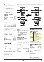
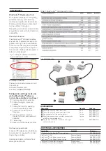
GALVANIC ISOLATION
Galvanic isolation is provided between
inputs and outputs as well as from the
supply voltage (3-port-isolation).
Test voltage:
Between power supply and
in-/outputs:
2.3 kV AC, 1 min
Between input and output
:
500 V AC; 1min
Isolation:
between in-/output against
earth:
ß
33 V AC
FUNCTIONS
Control behaviour
•
Signaller with adjustable switching
differential (On/Off control)
•
PID controller (two-point and
continuous)
•
Delta / Star / Off, or two-point
controller with full/partial load
switchover
•
2 x PID control (Heating / Cooling,
three-point, and continuous)
•
Three-point stepping controller
Control parameters are adjusted auto-
matically (self-tuning) or manually via
the front panel or using the BlueCon-
trol
®
software package.
The KS 45 has been prepared for con-
necting PMATune, in order to determi-
ne the optimum control parameters,
also with difficult control loops.
Setpoint functions
•
Adjustable setpoint gradient
0.01...9,999 per minute
•
Setpoint control
•
Master/Slave control
•
Program control with 4 segments
(setpoint/segment times)
•
Timer
•
Setpoint/Program control with
external shift
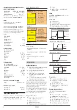
Timer
Time
t.SP
is adjustable from 0.1 to
9,999 minutes.
Timer start
•
On power up
•
Via control input
•
Selection in extended Operating Level
•
Direct selection of timer setting
Programmer
•
4 segments, can be disabled
•
Programmed time up to 9,999
minutes/segment
•
Start at process value
•
Program start via digital input or
front panel
Process value functions
•
Standard (process value X1)
Optionally:
•
Ratio control ((X1 + offset)/X2)
•
Difference control (X1 – X2)
•
Max. value selection from X1, X2
•
Min. value selection from X1, X2
•
Mean value selection from X1, X2
•
Switchover between X1 and X2
4
KS 45
safety isolation
functional isolation
Version 1
Version 2
power
relay OUT1
input INP1
input INP2
di 1 (contact)
di 1 (option
optocoupler)
output OUT3
RS 485
system
relay OUT2
front interface
power
relay OUT3
input INP1
input 2 (HC)
di 1 (contact)
di 1 (option
optocoupler)
optocoupler OUT1
RS 485
system
optocoupler OUT2
front interface
Fig. 2: Galvanic isolation
start
1
2
t.SP
End
Fig 3a: Timer modes 1 and 2
start
t.SP
3
4
End
Fig 3b: Timer modes 3 and 4
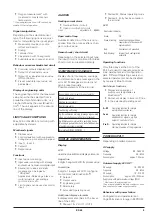
start
t.SP
Fig 3c: Timer mode 5
start
t.SP
SP
SP
SP.2
End
Fig 3d: Timer mode 6


