PMA KS 45 Скачать руководство пользователя страница 3

O

2

- measuring (option)

EMI-measuring by means of INP1

(high-impedance mV-inputs)

suitable for probes with

constant sensor temperature

(heated probes), setting by means

of parameter

measured sensor temperature

(non-heated probes), measuring by

means of INP2

ADDITIONAL INPUT INP2

(CURRENT)

Resolution:

>14 bits

Digital input filter:

adjustable ,0.0...999.9 s

Scanning cycle:

100 ms

Linearization:

as for INP1

Measurement value correction:

2-point or offset

Type:

single-ended

Current measurement

Input resistance:

approx. 49

Span start and span: anywhere between 0 and 20 mA
Scaling:

freely selectable, –1,999...9,999

Input circuit monitoring: 12,5% below span start (2 mA)

Heating current measurement

(via current transformer)

Input resistance:

approx. 49

Measurement span:

0...50 mA AC

Scaling:

freely selectable, –1,999....9,999 A

ADDITIONAL INPUT INP2

(UNIVERSAL, OPTION)

Resolution:

>14 bits

Digital input filter:

adjustable, 0.0...999.9 s

Scanning cycle:

100 ms

Linearization:

as for INP1

Measurement value correction:

2-point or offset

Type:

single-ended

except thermocouples

Thermocouples (Table 1)

Cold-junction compensation

Internal

- additional error:

typical:

max.:

ß_

0.5 K

ß

-2.5 K

External

0...100 °C

Remaining technical data as for INP1.

Resistive sensors (Table 2)

Connection technique:

3-wire

Measurement span

Remaining technical data as for INP1.

Current and voltage measurement

(Table 3)

Remaining technical data as for INP1

except:

Voltage input ranges –10 / 0...+10V and

-5...+5V not possible.

Millivolt input ranges: break monitoring

always active.

CONTROL INPUT DI1

Configurable as direct or inverse

switch or

push button

!

Contact input

Connection of potential-free contact that

is suitable for switching ‘dry’ circuits.

Switched voltage:

5 V

Switched current:

1 mA

Optocoupler input

For active control signals.

Nominal voltage:

24 V DC, external supply

Logic ‘0’:

-3...5 V

Logic ‘1’:

15...30 V

Current demand:

max. 6 mA

OUTPUTS

SURVEY OF OUTPUTS

Output

Purpose

OUT,1 OUT2
(relay, optional

optocoupler)

Control output ‘heating’ or ‘cool-

ing’(relay or optionalor Open/Closed;

Limit contact; Timer; optocoupler)

Programmer ‘End’ *

OUT3 (logic or

optional relay)

Same as OUT1 and OUT2

OUT3

(continuous)

Control output; Process value; Set-

point;Control deviation; Measure-

ment values of INP1/INP2; Trans-

mitter supply

* All logic signals can be ”OR-linked”.

Output values can also be forced via interface.

RELAY OUTPUTS OUT1, OUT2,

OUT3

Contact type:

normally open *

Max. contact rating:

500 VA, 250 V,

2A resistive load, 48...62 Hz,

Min. contact rating:

6V, 1 mA DC

Switching

cycles

(electrical):

for I=1A/2A:

?

800,000/500,000

(at 250V AC, resistive load)

* Versions with two relays OUT1 & OUT2

have a common terminal.

Note:

If the relays OUT1, 2 and 3 are used to

operate external contactors, these must be

fitted with RC snubber circuits to

manufacturer specifications to prevent

excessive voltage peaks at switch-off.

KS 45

3

V

14

13

12

16

15

11

mV

mA

V

17 18

INP2

INP1

OUT3

PWR

L

N

OUT1

OUT2

~90-260V

~24V

di1

8

7

6

3

2

1

5

3

4

(mV)

Data A

Data A

Data B

Data B

RGND

RGND

RS 485

KS45-1xY-xxxxx-xxx

Y

= 0, 1, 2, 3

V

14

13

12

16

15

11

mV

17 18

INP2

INP1

OUT3

PWR

L

N

OUT1

OUT2

~90-260V AC

~24V

di1

8

7

6

3

2

1

5

3

4

KS45-1xY-xxxxx-xxx

Y

= 4, 5

AC / DC

24VDC

1

2

top

16

15

17 18

System

16

15

17 18

System

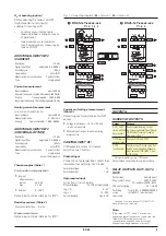
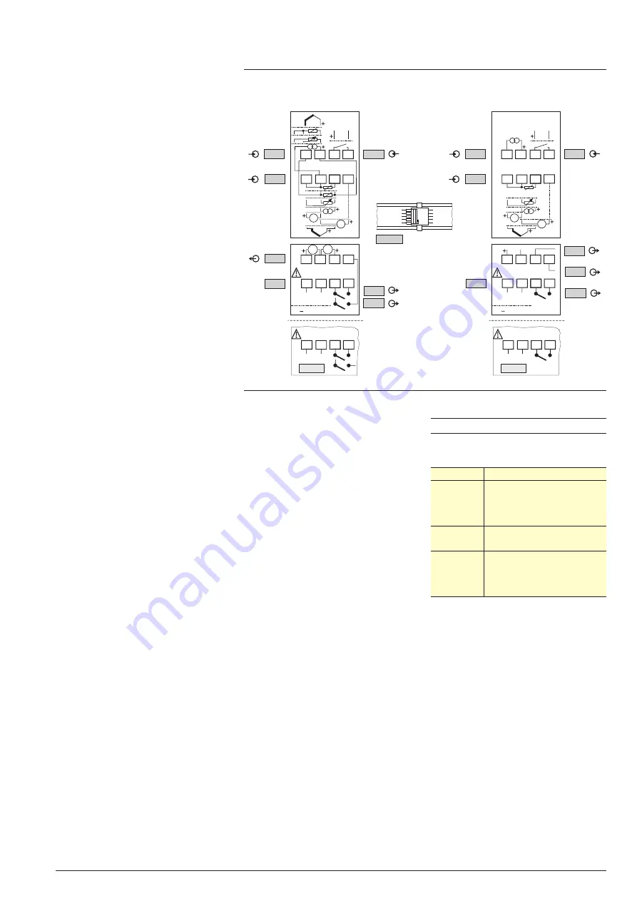
Fig. 1: Connecting diagram (

Œ

= Version 1,



= Version 2)

Содержание KS 45

Страница 1: ...l output is configurable as a voltage or current sig nal for controlling solid state relays or as a transmitter supply signal Galvanic isolation is provided between inputs and outputs as well as from the supply volta ge and the communication interfaces Mounting The compact KS 45 is clipped onto a top hat DIN rail and can also be un mounted very simply All connections are of the plug in type so tha...

Страница 2: ... Ω The BlueControl software enables the internal characteristic curve for the KTY 11 6 temperature sensor to be adapted Current and voltage measurement Table 3 Span start and span anywhere within the measurement range Scaling freely selectable 1 999 9 999 Input circuit 12 5 below span monitoring current start 2 mA 2 KS 45 Thermocouple type Measurement range Error Typical resol L Fe CuNi DIN 100 90...

Страница 3: ...T DI1 Configurable as direct or inverse switch or push button Contact input Connection of potential free contact that is suitable for switching dry circuits Switched voltage 5 V Switched current 1 mA Optocoupler input For active control signals Nominal voltage 24 V DC external supply Logic 0 3 5 V Logic 1 15 30 V Current demand max 6 mA OUTPUTS SURVEY OF OUTPUTS Output Purpose OUT 1 OUT2 relay opt...

Страница 4: ...nt controller with full partial load switchover 2 x PID control Heating Cooling three point and continuous Three point stepping controller Control parameters are adjusted auto matically self tuning or manually via the front panel or using the BlueCon trol software package The KS 45 has been prepared for con necting PMATune in order to determi ne the optimum control parameters also with difficult c...

Страница 5: ...k short circuit incorrect polarity Stored limit values Heating current alarm Control loop alarm Fault during self tuning E g Re calibration warning message is generated when a predefined operating time is reached E g Maintenance interval for a switching device message is generated when a predefined number of switching cycles is reached Internal fault RAM EEPROM DISPLAY AND OPERATION Display LCD du...

Страница 6: ...uous unattended operation Interference radiation Within the limits for Class B devices Immunity to interference Meets the test requirements for devi ces in industrial areas Evaluation criteria Surge interference partly has marked effects which decay after the interference stops With high levels of surge interference on 24 V AC mains leads it is possible that the device is reset With HF interferenc...

Страница 7: ...Text setting Definition of the display contents Hardware requirements A special PC adapter see Additional Accessories is required for connec ting to the controller Updates and demo software from www pma online de Table 4 BlueControl Versions and functions 1 2 3 4 5 Fig 6 Accessories Description Quantity Order no 1 Connector set with screw terminals 4 pcs 9407 998 07101 2 Connector set with spring ...

Страница 8: ... input with display and BluePort interface without options 0 90 260V AC 2 output relays INP2 as current input 0 20mA 18 30VAC 18 31VDC 2 0 20mA output relays INP2 as current input 0 1 di1 as contact input di1 as optocoupler input 1 INP2 as universal input 0 measurement di1 as contact input 2 INP2 di1 as optocoupler input as universal input 0 measurement 2 2 3 not on versions with optocoupler outpu...

Отзывы: