9 INSTALLING THE DIGITAL SYSTEM
Installation Manual
Planmeca ProOne 33
9.2 Configuring the Ethernet link
To enable communication through Ethernet link:
1. The correct Ethernet link cable needs to be connected to the X-ray unit (see section
9.1 “Connecting the Ethernet cable” on page 32).
2. The Ethernet settings of the ProOne X-ray unit must be configured (see below).
3. The IP Address and IP Port (5005) must then be entered in the DIDAPI configuration
program (Ethernet Interface settings). Refer to the Romexis Technical Manual for
details.
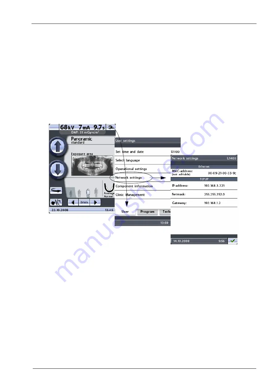
The Ethernet settings of the X-ray unit are configured from the control panel. Start by
touching the service spanner icon on the main display. The main display is the display that
is shown when the X-ray unit is switched on. Select the option Network settings (U1400)
on the User settings
display. The Network settings (U1400)
display will be shown.
On the Network settings (U1400)
display you can change the default settings. Note that
the settings shown above are just examples based on the network configuration of this
X-ray unit. They are NOT the defaults for your installation.
•
Ethernet
MAC address: MAC (Media Access Control) address is unit specific and it cannot be
changed.
•
TCP/IP
IP address: This field shows the Ethernet interface IP (Internet Protocol) address. The
IP address is a unique number assigned to this X-ray unit.
To change the IP address, touch the IP address field and enter the new address on
the number keyboard that appears. Save the new IP address by touching the green
check mark button, or exit the number display by touching the red cross button.
Netmask: This field shows the subnet mask.
To change the netmask, touch the Netmask
field and enter the new netmask on the
number keyboard that appears. Save the new netmask by touching the green check
mark button, or exit the number display by touching the red cross button.
Gateway: This field shows the gateway IP (Internet Protocol) address.
Service spanner
Содержание ProOne
Страница 1: ...PlanmecaProOne EN 10016257_12 installation manual ...
Страница 2: ......
Страница 38: ...10 POST INSTALLATION CHECK LIST 36 Planmeca ProOne Installation Manual ...
Страница 39: ...11 DIAGRAMS Installation Manual Planmeca ProOne 37 11 DIAGRAMS ...
Страница 40: ......
Страница 41: ......
Страница 43: ......
Страница 45: ......
Страница 47: ......
Страница 49: ......
Страница 51: ......
Страница 53: ......
Страница 55: ......
Страница 56: ......


