background image


i

P

REFACE


FCC Compliance Statement 

This device complies with part 15 of the FCC Rules. Operation is subjected to 
the following two conditions: 

1.  This device may not cause harmful interference, and 
2.  This device must accept any interference received, including interference 

that may cause undesired operation. 

FCC WARNING 

This equipment has been tested and found to comply with the limits for a Class B 
digital device, pursuant to Part 15 of the FCC Rules. These limits are designed to 
provide reasonable protection against harmful interference in a residential 
installation. 

This equipment generates, uses and can radiate radio frequency energy and, if 
not installed and used in accordance with the instructions, may cause harmful 
interference to radio communications. 

However, there is no guarantee that interference will not occur in a particular 
installation. If this equipment does cause harmful interference to radio or 
television reception, which can be determined by turning the equipment off and 
on, the user is encouraged to try to correct the interference by one or more of the 
following measures: 

Reorient or relocate the receiving antenna. 

• 

Increase the separation between the equipment and the receiver. 

• 

Connect the equipment into an outlet different from that to which the 
receiver is connected. 

• 

Consult the dealer or an experienced radio/TV technician for help. 

Caution: 

To comply with the limits for an FCC Class B computing device, always use the 
shielded signal cord supplied with this unit. 

The Federal Communications Commission warns that changes or modifications 
of the unit not expressly approved by the party responsible for compliance could 
void the user’s authority to operate the equipment. 

Содержание PE191M

Страница 1: ......

Страница 2: ...mmunications However there is no guarantee that interference will not occur in a particular installation If this equipment does cause harmful interference to radio or television reception which can be determined by turning the equipment off and on the user is encouraged to try to correct the interference by one or more of the following measures Reorient or relocate the receiving antenna Increase t...

Страница 3: ...take adequate measures Canadian Doc Notice For Class B Computing Devices This digital apparatus does not exceed the Class B limits for radio noise emissions from digital apparatus as set out in the Radio Interference Regulation of the Canadian Department of Communications Le présent appareil numérique n èmet pas de bruits radioélectriques dépassant les limites applicables aux appareils numériques ...

Страница 4: ...the cord is placed in an area where it will not be stepped on 4 Do not apply pressure to the LCD screen Excessive pressure may cause permanent damage to the display 5 Do not remove the cover or attempt to service this unit by yourself You may void the warranty Servicing of any nature should be performed only by an authorized technician 6 Safe storage of the LCD Monitor is in a range of 20 C to 60 ...

Страница 5: ...th ground connection Japan VCTF type 3 wires or with ground wire T mark approval is required U S VW 1 18AWG X 3C SVT with national approval as UL and or CSA approval number s Europe VDE ÖVE and or KEMA approval H05VV F 3G 0 75mm2 or equivalent Above power cord should bear with the type and manufacturer name on ...

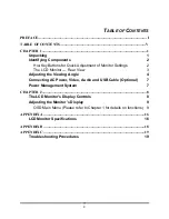
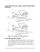
Страница 6: ...Rear View 3 Adjusting the Viewing Angle 4 Connecting AC Power Video Audio and USB Cable Optional 7 Power Management System 7 CHAPTER 2 8 The LCD Monitor s Display Controls 8 Adjusting the Monitor s Display 9 OSD Main Menu Please refer to Chapter 1 for details on functions 9 APPENDIX A 16 LCD Monitor Specifications 16 APPENDIX B 18 APPENDIX C 19 Troubleshooting Procedures 19 ...

Страница 7: ......

Страница 8: ...al cable 15 pin Monitor to PC Digital signal cable 24 pin optional Stereo Jack Audio Cable optional USB Cable optional Power cord Landing Strip User s manual CD Manual If you find that any of these items are missing or appear damaged contact your dealer immediately Do not throw away the packing material or shipping carton in case you need to ship or store the LCD Monitor in the future ...

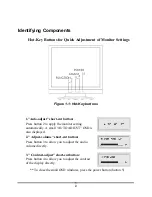
Страница 9: ... to apply the monitor setting automatically A small AUTO ADJUST OSD is also displayed 2 Adjust volume short cut button Press button 3 to allow you to adjust the audio volume directly 3 Contrast adjust short cut button Press button 4 to allow you to adjust the contrast of the display directly To close the small OSD windows press the power button button 5 ...

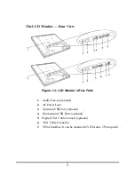
Страница 10: ...CD Monitor s Rear Ports 1 Audio Line in optional 2 AC Power Jack 3 Upstream USB Port optional 4 Downstream USB Ports optional 5 Digital VGA Cable Connect optional 6 VGA Cable Connector 7 VESA interface It can be mounted to VESA arm 75mm pitch ...

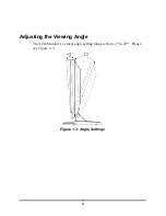
Страница 11: ...4 Adjusting the Viewing Angle The LCD Monitor s vertical angle setting range is from 3 to 20 Please see Figure 1 3 Figure 1 3 Angle Settings ...

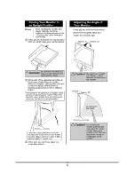
Страница 12: ...5 Raising Your Monitor to an Upright Position and Adjusting Monitor Angle ...

Страница 13: ...6 ...

Страница 14: ...or complies with the VESA DPMS version 1 0p power management proposal The VESA DPMS proposal provides four phases of power saving modes by detecting the horizontal or vertical sync signal When the LCD Monitor is in power saving mode or detects an incorrect timing the Monitor screen will go blank and the power LED indicator will start to blink ...

Страница 15: ...2 Adjustment Control Buttons These two buttons allow you to adjust the selected control functions in the OSD 3 Function Select Buttons These two buttons allow you to select the control functions in the OSD Press either button to scroll through the main menu and submenu items 4 Power Switch Push the power switch to turn the monitor on and off This switch is also a hot key button to close the OSD me...

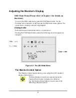
Страница 16: ...s highlighted Analog mode Each main menu and submenu item is covered below Pressing the OSD Menu button causes the following screen to appear an example Figure 2 2 The OSD Main Menu The Monitor Control Option The Monitor Control option allows you to adjust the LCD monitor s display characteristics With the Monitor Control icon selected press the Function Enter button to display the submenu Use the...

Страница 17: ...ol buttons resets H Position V Position Phase and Clock parameters GRAPH TEXT Press the Function Enter button to switch between the text and graphic options PORT SELECT Press the Adjust buttons to change input between VGA port and DVI digital port optional EXIT Pressing the Function Enter button exits the Monitor Control submenu OSD Control Option The OSD Control menu option lets you adjust the po...

Страница 18: ...between the lightest and darkest areas of the LCD monitor s display screen BRIGHTNESS Use the Adjustment Control buttons to adjust the light level on the LCD monitor s display screen It should be adjusted in conjunction with the Contrast item COLOR Use either of the Adjustment Control buttons to select the LCD monitor s color display The available options are 9300 6500 and User The 9300 and 6500 o...

Страница 19: ...ent Control buttons to scroll to the desired OSD display language The supported languages are German English French Spanish and Italian AUDIO VOLUME Use the Adjustment Control buttons to increase or decrease the volume of the LCD monitor s sound system INFORMATION The Information submenu option is a display only item that provides information on the display mode and firmware version EXIT Pressing ...

Страница 20: ...ct one of the following submenu options PORT SELECT Press the Adjust buttons to change input between VGA port and DVI digital port optional EXIT Pressing the Function Enter button exits the Monitor Control submenu OSD Control Option The OSD Control menu option lets you adjust the position of the OSD on the screen With the OSD Control icon selected press the Function Enter button to display the sub...

Страница 21: ...uttons to select one of the following submenu options CONTRAST Use the Adjustment Control buttons to adjust the difference between the lightest and darkest areas of the LCD monitor s display screen BRIGHTNESS Use the Adjustment Control buttons to adjust the light level on the LCD monitor s display screen It should be adjusted in conjunction with the Contrast item RESET Pressing either of the Adjus...

Страница 22: ...g the Function Enter button exits the Misc Control submenu OSD Exit Option Use the OSD Exit item to close the OSD program Press the Function Enter button with the OSD Exit item selected to exit the OSD program The OSD will close by itself if left inactive Note 1 NO VIDEO When the monitor is ON and there is no Video signal received the NO VIDEO message will be displayed 2 Signal out of monitor s su...

Страница 23: ...Control OSD Horizontal Position OSD Vertical Position OSD Timer Exit Graphic Control Contrast Brightness Color R G B Auto Level Reset Exit Misc Control Language Audio Volume Information Exit On Screen Display OSD OSD Exit Display Area mm 376 32x 301 056mm 19 inch diagonal Display Colors 16 7M Video Interface Analog port VGA Compatible Analog RGB 15 pin D Sub Separate Sync Composite Sync On Green D...

Страница 24: ...USB 50W max OFF 5W max Measured from AC inlet Dimensions WxHxD mm 419 x 420 x 241 1A Net Weight Kg Approx 6 5 1 Power Supply Built In Universal Input Off Line Power Supply Options Wall mounted bracket Arm mounted bracket VESA Compliance USB Ver1 1 Self Powered Hub 1up 2down stream ports Environment Operating Temperature 0 to 40 C Relative Humidity 10 to 85 Audio Two 1 Watt speakers with amplifier ...

Страница 25: ...GA 800x600 40 00 60 32 37 88 A D G 13 VESA 800x600 50 00 72 19 48 08 A D G 14 VESA 800x600 49 50 75 00 46 88 A D G 15 VGA 720x400 28 32 70 09 31 47 A G 16 XGA 1024x768 65 00 60 00 48 36 A D G 17 VESA 1024x768 75 00 70 07 56 48 A D G 18 VESA 1024x768 78 75 75 03 60 02 A D G 19 1024x768 71 64 66 13 53 96 A D G 20 VESA 1152x864 108 00 75 00 67 50 A D G 21 1152x870 100 75 06 68 68 A D G 22 VESA 1280x9...

Страница 26: ...t or you can select the window shut down screen 2 After you have the wallpaper loaded open the OSD and select the Clock function Press the top or bottom Adjustment Control button and continue pressing the button until you see vertical dark and light lines across the screen 3 When you can see distinct light and dark vertical bands stop pressing the Adjustment Control button Now press the opposite t...

Страница 27: ...work connect your PC system to another external CRT If your PC System functions properly with a CRT Monitor but it does not function with the LCD Monitor and the LCD Monitor s power LED is blinking the output timing of the PC s VGA card may be out of the LCD s synchronous range Please change to an alternate mode listed in Addendum or replace the VGA card and repeat steps 1 and 2 4 If the PC doesn ...

Страница 28: ...6200502511 01 04 ...

Отзывы: