XC-IS21MD
62
Step No.
Operation Keys and Operation Method
FL Display
Status
Remarks
1
Short circuit MECH TEST MODE during the
EJECT
Test mode
power ON.
(Fig.6-1)
2
Insert the test disc GGF1328 (MMD-212).
LOADING
GRT AJST
3
Perform “ Normal Adjustment ” (step 3, step 4).
AUTO AJST
4
Press the REC key.
TEST PLAY
TEST PLAY mode
5
Press the ENTER key and display the inner
ADRES 0050
circumference address.
6
Press the PLAY key and display the C1 error for
a0050 c0015
Check that the jitter value meets the standard
the inner circumference.
value of the following table.
GGF1328 (MMD-212) jitter value
7
Press the CHARA key.
A0062 c0013
Seven data are acquired, the largest and the
AVE. c0012
smallest value are discarded, and fixed display
is made for the mean value of the remaining
five data. Check that this value is 200 or less.
Step No.
Operation Keys and Operation Method
FL Display
Status
Remarks
7
Press the REC key.
of-04 c0020
The C1 error with application of a focus offset of
about 0.4
µ
m on the – side is displayed.
The jitter value (J–) at this time is recorded.
8
When J+ is larger than J-, press the REC key and
of+04 c0032
display the C1 error when the focus offset is
applied up to +0.4
µ
m.
(Do nothing when J- is larger than J+.)
9
Change the value with the ASES Key (Up) and the
of+04 c0032
When the smaller offset of the jitter value has
REC MENU key (Down)until the value becomes the
of+03 c0025
been corrected mistakenly, press the ENTER
same.
of+02 c0020
key and return to step 4.
10
Press the PLAY key.
COMPLETE
The mean value of the changed set value and
the offset of the other setting limit is written into
the EEPROM as the compensation offset.
11
Power OFF
Test mode is ended.
6
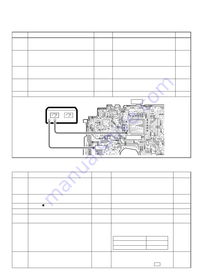
Defocus adjustment
Connection diagram
Jitter Meter
LEVEL
JITTER
GND
MD CORE MAIN UNIT
SIDE A
REFO
EFM MON
Inner circumference
31 nsec or less
Intermediate circumference
29 nsec or less
Outer circumference
29 nsec or less
7
Jitter/C1 Error Check at the time of Playback
Содержание XC-IS21MD
Страница 35: ...XC IS21MD 35 A B C D 5 6 7 8 5 6 7 8 L E CN4 E CN2 J102 J104 C CN40 J140 PB PB PB PB REC REC REC REC ...
Страница 51: ...XC IS21MD 51 A B C D 1 2 3 4 1 2 3 4 FRONT PANEL ASSY M Q5902 Q5901 Q5903 ANP7301 B SIDE B M ...
Страница 94: ...94 XC IS21MD 8 1 PANEL FACILITIES 8 PANEL FACILITIES AND SPECIFICATIONS Front Panel ...


