32
A
B
C
D
1
2
3
4
1
2
3
4
PRO-507PU
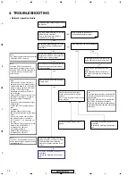
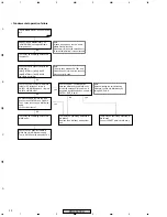
Doesn't "Home Media Gallery" on
"HOME MENU" become selectable
after power-on?
Note:
It takes a short while to start "Home
Media Gallery" function.
Please wait for about 40 seconds until
"Home Media Gallery" turns selectable.
Check each wire connection with the
MAIN ass'y.
[HN1]CN7851<=>[M14]CN4017
[HN2]CN7901<=>[M15]CN4016
Isn't there any failure?
"Home Media Gallery" does not work at
all!
There may be something defective in
the product.
Check the power supply for HNM ass'y.
Is there +5V voltage on 1st pin in
CN7901 of HNM side and on 1st pin in
CN4016 of MAIN side?
Check the FET transistor switch in
MAIN ass'y for HNM power supply.
That is Q4102 and the parts around it.
To make analysis, remove the wire
ass'y between CN7901 and CN4016.
Then, check the voltage in MAIN side
again.
Is +5V still not there?
Note:
The wire ass'y between CN7901 and
CN4016 has only three wires, though 4-
pin connector is used.
There may be something defective in
HNM ass'y.
Replace the HNM ass'y with another
one.
There may be something defective in
MAIN ass'y.
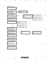
Check the UART communication
between HNM ass'y and MAIN ass'y.
Almost 35 seconds after power-on, is
any pulse signal observed on 2nd pin in
CN7851: RXD_DLNA?
Note:
After completing the self-initializing,
HNM ass'y notice it to MAIN ass'y by
using RXD_DLNA.
There may be something defective in
MAIN ass'y.
Check the UART path in MAIN ass'y.
No
yes
yes
yes
No
No
No
No
• Fundamental operation failure
Содержание PRO-507PU
Страница 11: ...11 A B C D 5 6 7 8 5 6 7 8 PRO 507PU ELITE AWV2310 AWW1158 for AWV2311 B for AWV2311 A REGULAR AWV2313 AWW1154 ...
Страница 15: ...15 A B C D 5 6 7 8 5 6 7 8 PRO 507PU ...
Страница 16: ...16 A B C D 1 2 3 4 1 2 3 4 PRO 507PU 8620 BLOCK HN MODULE ASSY 1 6 1 2 2 2 2 2 Large size SCH diagram ...
Страница 17: ...17 A B C D 5 6 7 8 5 6 7 8 PRO 507PU ...
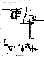
Страница 18: ...18 A B C D 1 2 3 4 1 2 3 4 PRO 507PU 2 5 HN MODULE ASSY 2 6 86220 DDR BLOCK HN MODULE ASSY 2 6 ...
Страница 19: ...19 A B C D 5 6 7 8 5 6 7 8 PRO 507PU ...
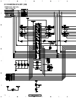
Страница 20: ...20 A B C D 1 2 3 4 1 2 3 4 PRO 507PU 2 6 HN MODULE ASSY 3 6 ETHERNET BLOCK HN MODULE ASSY 3 6 ...
Страница 21: ...21 A B C D 5 6 7 8 5 6 7 8 PRO 507PU ...
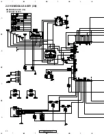
Страница 22: ...22 A B C D 1 2 3 4 1 2 3 4 PRO 507PU 2 7 HN MODULE ASSY 4 6 HNM USB BLOCK HN MODULE ASSY 4 6 ...
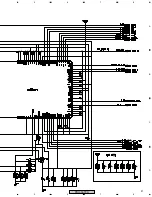
Страница 23: ...23 A B C D 5 6 7 8 5 6 7 8 PRO 507PU USB POWER SECTION ...
Страница 24: ...24 A B C D 1 2 3 4 1 2 3 4 PRO 507PU 2 8 HN MODULE ASSY 5 6 HNM IO BLOCK HN MODULE ASSY 5 6 ...
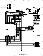
Страница 25: ...25 A B C D 5 6 7 8 5 6 7 8 PRO 507PU ...
Страница 26: ...26 A B C D 1 2 3 4 1 2 3 4 PRO 507PU 2 9 HN MODULE ASSY 6 6 HNM POWER BLOCK HN MODULE ASSY 6 6 ...
Страница 27: ...27 A B C D 5 6 7 8 5 6 7 8 PRO 507PU For Power Sequence ...
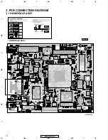
Страница 29: ...29 A B C D 5 6 7 8 5 6 7 8 PRO 507PU HN MODULE ASSY SIDE B ANP2148B ...
Страница 34: ...34 A B C D 1 2 3 4 1 2 3 4 PRO 507PU Block Diagram ...
Страница 35: ...35 A B C D 5 6 7 8 5 6 7 8 PRO 507PU ...
Страница 36: ...36 A B C D 1 2 3 4 1 2 3 4 PRO 507PU ...
Страница 37: ...37 A B C D 5 6 7 8 5 6 7 8 PRO 507PU ...
Страница 38: ...38 A B C D 1 2 3 4 1 2 3 4 PRO 507PU ...
Страница 39: ...39 A B C D 5 6 7 8 5 6 7 8 PRO 507PU ...

