background image

(No.52097)

DT-V1910CG/U

INSTRUCTIONS

DT

-V1910CG

MUL

TI-FORMA

T MONIT

OR

V

OLUME

SLO

T 1

A

B

DEGA

USS

MENU

MUTING

SCREENS

CHECK

ASPECT

AREA

MARKER

UNDER SCAN

PULSE CR

OSS

COLOR

OFF

SLO

T 2

C

D

SLO

T

 3

PO

WER

E

F

INPUT SELECT

For Customer Use:

Enter below the Serial No. which is located on the rear of

the cabinet. Retain this information for future reference.

Model No.

:

DT

-V1910CG

Serial No.

:

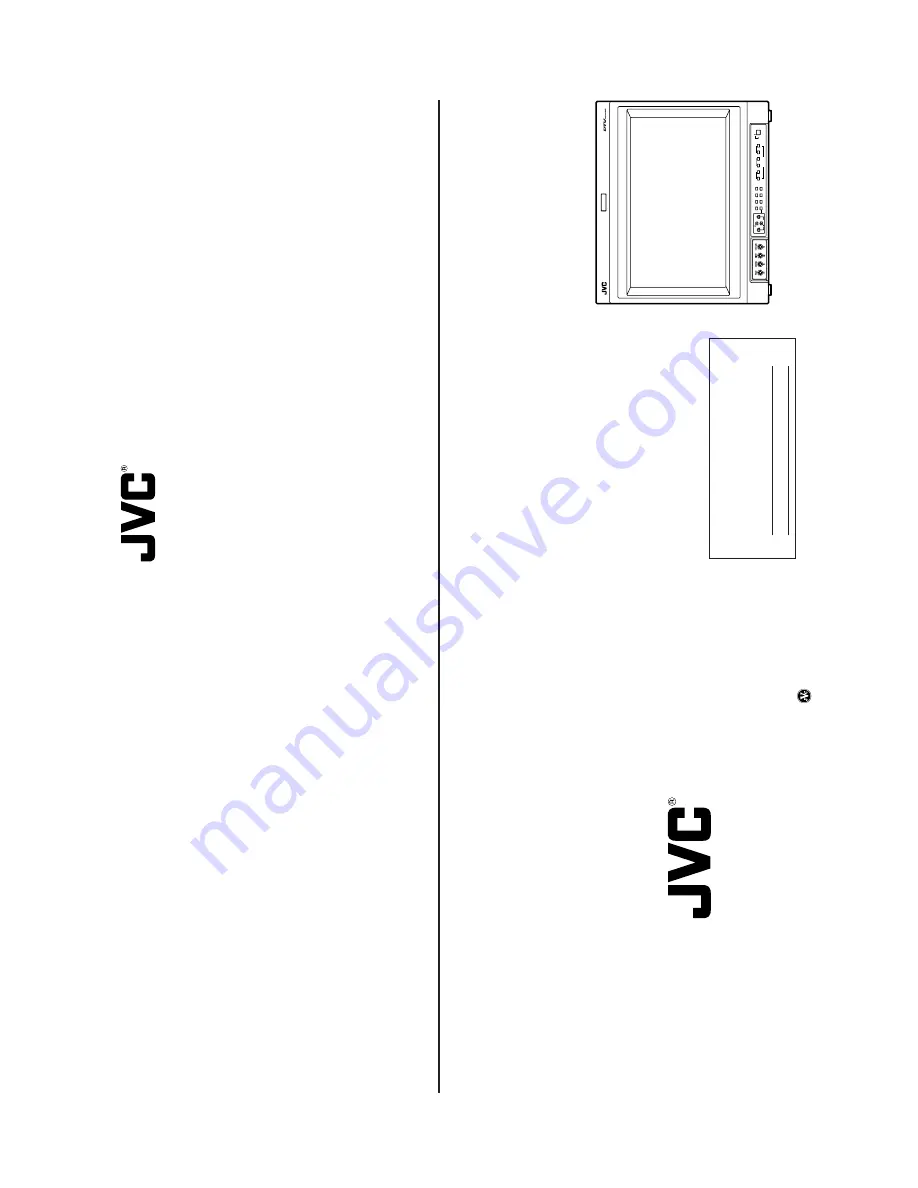
The illustration above shows the DT

-V1910CG with provided

wide mask attached.

LCT1316-001B

JVC PROFESSIONAL PRODUCTS COMPANY

DIVISION OF US JVC CORP.

1700 Valley Road Wayne, N.J. 07470

JVC CANADA INC.

21 Finchdene Square, Scarborough Ontario M1X 1A7

©

 2003 VICT

OR COMP

ANY

 OF JAP

AN, LIMITED

Printed in Japan

0103-MA-UN-VP

DT-V1910CG MULTI-FORMAT MONITOR

OPERATING INSTRUCTIONS

Содержание DT-V1910CG

Страница 1: ...ed on the rear of the cabinet Retain this information for future reference Model No DT V1910CG Serial No The illustration above shows the DT V1910CG with provided wide mask attached LCT1316 001B JVC PROFESSIONAL PRODUCTS COMPANY DIVISION OF US JVC CORP 1700 Valley Road Wayne N J 07470 JVC CANADA INC 21 Finchdene Square Scarborough Ontario M1X 1A7 2003 VICTOR COMPANY OF JAPAN LIMITED Printed in Jap...

Страница 2: ...o not use a magnet eraser to degauss the monitor s cathode ray tube from the outside Doing so may distort its aperture grill and cause a malfunction In order to prevent any fatal accidents caused by misoperation or mishandling the monitor be fully aware of all the following precautions WARNINGS To prevent fire or shock hazard do not expose this monitor to rain or moisture Dangerous high voltages a...

Страница 3: ... the cabinet Retain this information for future reference Serial No Model No DT V1910CG SAFETY PRECAUTIONS 2 CONTROLS AND FEATURES 4 CONTROLS AND FEATURES INPUT CARD OPTIONAL 7 PREPARATION 9 BASIC MENU OPERATIONS MAIN MENU SETUP MENU 11 HOW TO USE MAIN MENU 13 HOW TO USE SETUP MENU 16 HOW TO USE EXTERNAL CONTROL 21 TROUBLESHOOTING 23 SELF CHECK INDICATIONS 25 SPECIFICATIONS 26 CONTENTS DT V1910CG ...

Страница 4: ... S A only CAUTION Changes or modifications not approved by JVC could void the user s authority to operate the equipment NOTE This equipment has been tested and found to comply with the limits for a Class A digital device pursuant to Part 15 of the FCC Rules These limits are designed to provide reasonable protection against harmful interference when the equipment is operated in a commercial environ...

Страница 5: ... confirm the synchronized sections When the PULSE CROSS button is pressed while lit the light goes off and the normal screen is restored NOTE This function is invalid with the RGB input screen COLOR OFF button lamp When you press the COLOR OFF button the button lights and the screen becomes mono chrome Only the brightness signal is displayed When the COLOR OFF button is pressed while lit the light...

Страница 6: ...T terminals are bridge connected auto termination Synchronized signal input output terminals Input IN and output OUT terminals for the vertical horizontal or complex synchronized signals To use these terminals set SYNC SELECT to EXT Refer to SYNC SELECT on page 17 for more information Audio input output terminals Input IN and output OUT terminals for the analog audio signals The IN and OUT termina...

Страница 7: ...I2 Input IN and output OUT terminals for the analog audio signals The IN and OUT terminals are bridge connected Connection terminal Attach to the connection terminal of your Multi Format Monitor 1 Compatible signal formats 480 60i 576 50i 2 3 4 AUDIO 2 AUDIO 1 OUT IN SWITCHED OUT SDI 1 SDI 2 IN IN 1 2 3 4 E AUDIO HD SDI 1 IN OUT 2 1 E AUDIO HD SDI 2 IN OUT 9 PREPARATION 1 Turn off the Multi Format...

Страница 8: ...trix 1 About Displays 1 Not displayed when an RGB signal is input 2 Displayed only when the screen ratio is 16 9 Not displayed when an RGB signal is input When some items are not displayed depending on the input signals subsequent items will move up Position of the menu varies depending on the type of signal SETUP MENU Items Functions 1 FUNCTION SETTING Selects the control systems for the COLOR SY...

Страница 9: ...s pressed SETUP MENU is displayed on the screen 2 Select PICTURE SUB ADJ by pressing the button then press the button 3 Select sub menu by pressing the button several times then press the button The adjustment bar is displayed at the bottom or top of the screen 4 Select the desired setup item by pressing the and buttons several times 5 Press the and or buttons as many times as required to obtain t...

Страница 10: ...nu reset EXIT MENU ADJUST SELECT INPUT A INPUT B Status of SLOT1 INPUT C INPUT D Status of SLOT2 INPUT E INPUT F Status of SLOT3 VIDEO 1 VIDEO 2 With VIDEO input card is installed COMP RGB With Component RGB input card is installed SDI1 SDI2 With SDI input card is installed HD SDI1 HD SDI2 With HD SDI input card is installed NOTES If an input card is compatible with EMBEDDED AUDIO an asterisk is d...

Страница 11: ...hen different signal cables are connected to each INPUT A and INPUT C and signals are input to the each of them Preparation for the AUTO INPUT function See below illustration 1 Insert HD SDI input card to SLOT1 and SDI input card to SLOT2 both cards need to be compatible with AUTO INPUT then connect the signal cable 2 Input HD SDI signal or D1 SDI signal to HD SDI input card SYNC SELECT Synchroniz...

Страница 12: ...gnal is input only CONTRAST BRIGHT and CHROMA are displayed 19 DISTORTION ADJ PINCUSHION 00 PIN BALANCE 00 PARALLELOGRAM 00 TRAPEZOID 00 ROTATION 00 sub menu reset EXIT MENU ADJUST SELECT DISTORTION ADJ Compensates the picture distortion Press the button to display the setting menu illustrated on the right PINCUSHION Compensates pincushion picture distortion 20 00 20 Expands both left and right si...

Страница 13: ...VER LEVEL Sets the input level s lower limit indicated in red for the 3COLORS display 8dB 6dB 4dB 2dB BAR BRIGHTNESS Selects the brightness of the AUDIO LEVEL METER display HIGH Brighter LOW Darker AUDIO LEVEL METER display example LEVEL METER ch 1 8 BAR TYPE 3COLORS OVER LEVEL 8dB 6dB 4dB 2dB REFERENCE LEVEL 20dB 18dB Audio channels and OVER REFERENCE level indication HOW TO USE SETUP MENU cont d...

Страница 14: ...d Wrong color Unnatural picture Shaking picture Points to be checked Is the power plug loosened or disconnected Is the main power turned OFF Is the signal cable disconnected Is the power of the connected component ON Is the signal output from the connected component Is the input signal selected correctly Is the input signal adapted to the monitor s specification Are any of the self check indicator...

Страница 15: ...omenon is due to mutual interference it is not a malfunction Move the monitors away from each other until the interference disappears or turn the power off on any monitor that is not being used VOLUME SLOT 1 A B DEGAUSS MENU MUTING SCREENS CHECK ASPECT AREA MARKER UNDER SCAN PULSE CROSS COLOR OFF SLOT 2 C D SLOT 3 POWER E F INPUT SELECT Reference pages 4 19 5 20 21 22 Damper line When black vertic...

Страница 16: ...connector 9 pin compliant to RS 232C Audio Output 1 W monaural Built in Speaker 8 cm 3 1 8 round x 1 Environmental Conditions Operating temperature 5 C 35 C 41 F 95 F Operating humidity 20 80 non condensing Power Requirements 120 230 V AC 50 Hz 60 Hz Power Consumption 1 8A 1 0A when input card is inserted Max 2 1 A 1 2 A when input card is inserted Dimensions Width 440 mm 17 3 8 Height 375 mm 14 7...

Страница 17: ...monaural RCA pin x 4 0 5 V rms high impedance The input IN and output OUT terminals are bridge connected Required slots 1 Power consumption 14 V DC 0 25 A 7 V DC 0 15 A Weight 0 5 kg 1 1 lbs Dimensions W x H x D 43 mm x 154 5 mm x 191 9 mm 1 3 4 x 6 1 8 x 7 5 8 IF C01SDG SDI INPUT CARD Type SDI input card for Multi Format Monitor Inputs Outputs Digital input SDI 1 SDI 2 2 lines BNC connector x 2 0...

Отзывы: