background image

6

A

B

C

D

1

2

3

4

1

2

3

4

PRO-507PU

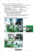
 Replacement of AWV2311: HOME NETWORK MODULE ass'y

There are two types of HOME NETWORK MODULE ass'y in interface with MAIN ass'y,
and only AWV2311-B /J is available as a service parts ass'y.

AWV2311- A /J

AWV2311- B /J

J7601: ADX3483

yes

no

CN7802: KM200NA3L

no

yes

Connection with MAIN ass'y Figure A

Figure B

When AWV2311-A /J is used in the product, order ADX3484 in addition, 

and connect it with MAIN ass'y as shown in Figure B.
Or perform the following steps as shown in Figure A. 

1. Take off ADX3483 from the defective ass'y
2. Solder it to the same point (4th pin in IC7803) on a service parts ass'y
3. Fix the wire by bond-lock, and then connect it with MAIN ass'y 

When AWV2311-B /J is used in the product,

replace the defective ass'y with a service parts ass'y as shown in Figure B.

Figure A: AWV2311-A /J

Figure B: AWV2311-B /J


Fix the wire by bond-lock.

Fix the wire by bond-lock.

4th pin in IC7803

4th pin in IC7803

ADX3484

ADX3484

CN7802

CN7802

M17

M17

M17

M17

ADX3483

ADX3483

ADX3485

ADX3485


Fix the wire by bond-lock.

4th pin in IC7803

ADX3484

CN7802

M17

M17

ADX3483

ADX3485

Содержание PRO-507PU

Страница 1: ...LAY This service manual should be used together with the following manual s Model No Order No Remarks PDP 5071PU KUCXC ARP3354 SAFETY INFORMATION EXPLODED VIEWS AND PARTS LIST BLOCK DIAGRAM PCB PARTS LIST ADJUSTMENT IC INFORMATION etc ARP3355 SCHEMATIC DIAGRAM and PCB CONNECTION DIAGRAM CONTENTS 1 CONTRAST OF MISCELLANEOUS PARTS 2 2 BLOCK DIAGRAM AND SCHEMATIC DIAGRAM 10 2 1 OVERALL WIRING DIAGRAM...

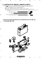
Страница 2: ...en ordering resistors first convert resistance values into code form as shown in the following examples Ex 1 When there are 2 effective digits any digit apart from 0 such as 560 ohm and 47k ohm tolerance is shown by J 5 and K 10 Ex 2 When there are 3 effective digits such as in high precision metal film resistors 5 6 1 4 7 3 R 5 0 1 R 0 5 6 2 1 560 47k 0 5 1 RD1 4PU J RD1 4PU J RN2H K RS1P K 56 x ...

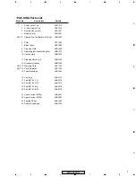
Страница 3: ...908 8 Cleaning Cloth AED1285 9 Operating Instructions English ARB1573 10 Caution Card ARM1239 11 Cleaning Caution U ARM1303 12 Accessory Caution ARM1304 NSP 13 Warranty Card ARY1123 NSP 14 Card Register ARY1156 15 Polyethlene Bag AHG1394 16 Vinyl Bag AHG1347 17 Pad 507EL T L AHA2576 18 Pad 507EL T R AHA2577 19 Pad 507EL B L AHA2578 20 Pad 507EL B R AHA2579 21 Under Carton 507EL AHD3491 22 Upper Ca...

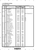
Страница 4: ...ton Sheet U AAK2895 Not used P13 29 Function Button Sheet U E Not used AAK2903 P13 30 Input Cover Label U AAX3363 Not used P13 30 Input Cover Label U E Not used AAX3404 FRONT SECTION P15 3 Front Case Assy 507PU AMB2917 AMB2918 P15 5 Pioneer Name Plate AAM1098 Not used P15 5 Elite Badge Not used AAM1102 PDP SERVICE ASSY P25 1 PDP SERVICE Assy AWU1212 AWU1227 P25 1 NSP 2 P Chassis 507 Assy AWU1148 N...

Страница 5: ...5 No 5 No 3 No 3 No 5 No 5 No 6 No 6 POD Stay B POD Stay B PMB30P080FNI PMB30P080FNI AMZ30P060FTB AMZ30P060FTB AMZ30P060FTB AMZ30P060FTB BMZ30P060FTB BMZ30P060FTB BMZ30P060FTB BMZ30P060FTB No 5 No 5 No 4 No 5 Note see next page No 5 No 5 No 1 No 5 No 5 No 2 No 5 No 5 No 3 No 5 No 5 No 6 POD Stay B PMB30P080FNI AMZ30P060FTB AMZ30P060FTB BMZ30P060FTB BMZ30P060FTB ...

Страница 6: ...igure B Or perform the following steps as shown in Figure A 1 Take off ADX3483 from the defective ass y 2 Solder it to the same point 4th pin in IC7803 on a service parts ass y 3 Fix the wire by bond lock and then connect it with MAIN ass y When AWV2311 B J is used in the product replace the defective ass y with a service parts ass y as shown in Figure B Figure A AWV2311 A J Figure B AWV2311 B J F...

Страница 7: ...CKSSYB104K10 R4113 Not used RS1 16SS102J R4114 Not used RS1 16SS223J R4115 Not used RS1 16SS104J R4169 Not used RS1 10S0R0J BOARD IF BLOCK R4031 RS1 16SS0R0J Not used R4011 Not used RS1 16S0R0J R4032 Not used RS1 16SS0R0J CN4011 Not used AKM1274 CN4016 Not used AKM1275 CN4017 Not used AKM1235 AV SW BLOCK C4703 Not used CKSRYB105K10 C4755 C4756 Not used CCG1205 R4713 Not used RS1 16SS101J R4821 Not...

Страница 8: ...W1154 AWW1158 Remarks R9200 RS1 16SS0R0J Not used R9201 Not used RS1 16SS0R0J AWW1158 and AWW1154 are constructed the same except for the following SIDE ASSY Mark Symbol and Description Part No AWW1157 AWW1155 Remarks R9141 RS1 16SS0R0J Not used R9142 Not used RS1 16SS0R0J JA9101 AKB1303 AKB1304 JA9102 AKB1305 AKB1306 AWW1155 and AWW1157 are constructed the same except for the following Note For S...

Страница 9: ...86 Mark No Description Part No Mark No Description Part No MISCELLANEOUS L 7852 7854 LCTAWR47J2520 F 7852 7858 ATX1066 X 7851 ASS1211 CN7851 CKS3888 RESISTORS R 7851 RS1 16SS37R4F R 7859 7861 7875 RS1 16SS75R0F R 7876 7886 RS1 16SS1501F R 7877 7887 RS1 16SS6801F R 7879 7888 RS1 16SS3301F R 7880 7893 RS1 16SS5101F R 7895 7897 RS1 16SS75R0F Other Resistors RS1 16SS J CAPACITORS C 7851 7858 7861 7862...

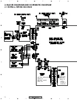
Страница 10: ...10 A B C D 1 2 3 4 1 2 3 4 PRO 507PU 2 BLOCK DIAGRAM AND SCHEMATIC DIAGRAM 2 1 OVERALL WIRING DIAGRAM AWV2310 ELITE AWW1153 ELITE AWV2310 AWW1155 AWV2313 REGULAR AWW1156 REGULAR AWV2313 AWW1157 ...

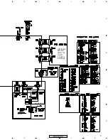
Страница 11: ...11 A B C D 5 6 7 8 5 6 7 8 PRO 507PU ELITE AWV2310 AWW1158 for AWV2311 B for AWV2311 A REGULAR AWV2313 AWW1154 ...

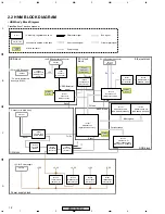
Страница 12: ...tch to USB Receptacle Connector USB Differencial signal 5V IC7753 BR93L46RFJ W EEPROM 1kbit IC7751 TC74LCX125 3 state Buffer Tx Rx Tx Rx IC7857 TC74LCX125 3 state Buffer Reset Reset Reset Reset IC7851 PST596IN Reset IC IC7852 TC7S00F NAND IC7852 TC74LCX04 Inverter Reset 3 3V 2 5V 5 0V 1 2V 5 0V IC7902 NJM2846DL3 25 Regulator IC IC7903 LTC3412EFE SW Reg IC IC7904 LTC3412EFE SW Reg IC RJ 45 Ethernet...

Страница 13: ...scription voltage V pin 1 5V I 5V power supply 5 0 1 2 N C No use in this model 2 3 GND 0 3 4 GND 0 4 HNM Ass y USB cable HN3 CN7801 pin pin name I O description voltage V 1 5V O 5V for USB bus power 5 0 2 D I O USB differential signal minus 3 3 0 3 D I O USB differential signal plus 3 3 0 4 GND 0 5 Sheild 0 HNM Ass y MTB MAIN Ass y HN7 CN7802 CN4011 pin pin name I O description voltage V pin 1 N ...

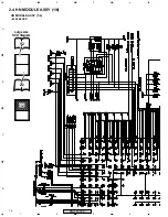
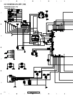
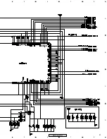
Страница 14: ...14 A B C D 1 2 3 4 1 2 3 4 PRO 507PU 2 4 HN MODULE ASSY 1 6 8620 BLOCK HN MODULE ASSY 1 6 1 2 2 2 1 2 Large size SCH diagram ...

Страница 15: ...15 A B C D 5 6 7 8 5 6 7 8 PRO 507PU ...

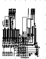
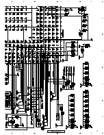
Страница 16: ...16 A B C D 1 2 3 4 1 2 3 4 PRO 507PU 8620 BLOCK HN MODULE ASSY 1 6 1 2 2 2 2 2 Large size SCH diagram ...

Страница 17: ...17 A B C D 5 6 7 8 5 6 7 8 PRO 507PU ...

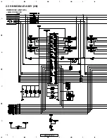
Страница 18: ...18 A B C D 1 2 3 4 1 2 3 4 PRO 507PU 2 5 HN MODULE ASSY 2 6 86220 DDR BLOCK HN MODULE ASSY 2 6 ...

Страница 19: ...19 A B C D 5 6 7 8 5 6 7 8 PRO 507PU ...

Страница 20: ...20 A B C D 1 2 3 4 1 2 3 4 PRO 507PU 2 6 HN MODULE ASSY 3 6 ETHERNET BLOCK HN MODULE ASSY 3 6 ...

Страница 21: ...21 A B C D 5 6 7 8 5 6 7 8 PRO 507PU ...

Страница 22: ...22 A B C D 1 2 3 4 1 2 3 4 PRO 507PU 2 7 HN MODULE ASSY 4 6 HNM USB BLOCK HN MODULE ASSY 4 6 ...

Страница 23: ...23 A B C D 5 6 7 8 5 6 7 8 PRO 507PU USB POWER SECTION ...

Страница 24: ...24 A B C D 1 2 3 4 1 2 3 4 PRO 507PU 2 8 HN MODULE ASSY 5 6 HNM IO BLOCK HN MODULE ASSY 5 6 ...

Страница 25: ...25 A B C D 5 6 7 8 5 6 7 8 PRO 507PU ...

Страница 26: ...26 A B C D 1 2 3 4 1 2 3 4 PRO 507PU 2 9 HN MODULE ASSY 6 6 HNM POWER BLOCK HN MODULE ASSY 6 6 ...

Страница 27: ...27 A B C D 5 6 7 8 5 6 7 8 PRO 507PU For Power Sequence ...

Страница 28: ...below 3 The parts mounted on this PCB include all necessary parts for several destinations For further information for respective destinations be sure to check with the schematic diagram 4 View point of PCB diagrams Symbol In PCB Diagrams Symbol In Schematic Diagrams Part Name B C E D D G G S S B C E B C E D G S B C E B C E B C E Transistor Transistor with resistor Field effect transistor Resistor...

Страница 29: ...29 A B C D 5 6 7 8 5 6 7 8 PRO 507PU HN MODULE ASSY SIDE B ANP2148B ...

Страница 30: ...ith examining the user s manual of the server check the server operation in detail There may be something defective in HNM ass y Replace the HNM ass y with another one No Before PDP turned on has the network server been turned on and connected to PDP with a network cable Jump and refer to the sheet of Fundamental operation failure yes yes yes Note The network server should be connected before the ...

Страница 31: ...rely attached One end is attached to CN7802 or the 4th pin of IC7803 in HNM ass y The other end is attached to CN4011 in MAIN ass y There may be something defective in HNM ass y Replace the HNM ass y with another one Even if you use any USB device available can t the symptom be improved Note One of the supported video format is WMV Below is the URL from which some WMV files of 720p resolution are ...

Страница 32: ... MAIN ass y for HNM power supply That is Q4102 and the parts around it To make analysis remove the wire ass y between CN7901 and CN4016 Then check the voltage in MAIN side again Is 5V still not there Note The wire ass y between CN7901 and CN4016 has only three wires though 4 pin connector is used There may be something defective in HNM ass y Replace the HNM ass y with another one There may be some...

Страница 33: ... PRO 507PU 5 IC INFORMATION RTL8100CL LF HN MODULE Assy IC7754 Ethernet Controller IC Pin Arrangement The information shown in the list is basic information and may not correspond exactly to that shown in the schematic diagrams ...

Страница 34: ...34 A B C D 1 2 3 4 1 2 3 4 PRO 507PU Block Diagram ...

Страница 35: ...35 A B C D 5 6 7 8 5 6 7 8 PRO 507PU ...

Страница 36: ...36 A B C D 1 2 3 4 1 2 3 4 PRO 507PU ...

Страница 37: ...37 A B C D 5 6 7 8 5 6 7 8 PRO 507PU ...

Страница 38: ...38 A B C D 1 2 3 4 1 2 3 4 PRO 507PU ...

Страница 39: ...39 A B C D 5 6 7 8 5 6 7 8 PRO 507PU ...

Отзывы: