background image

Operating Instructions
Mode d’emploi
Manual de instrucciones

Plasma Display
Écran à plasma
Pantalla de plasma

PDP-5004
PDP-5014
PDP-4304
PDP-4314

Register Your Product on

www.pioneerelectronics.com

Содержание PDP-4304

Страница 1: ...Operating Instructions Mode d emploi Manual de instrucciones Plasma Display Écran à plasma Pantalla de plasma PDP 5004 PDP 5014 PDP 4304 PDP 4314 Register Your Product on www pioneerelectronics com ...

Страница 2: ...terference to radio or television reception which can be determined by turning the equipment off and on the user is encouraged to try to correct the interference by one or more of the following measures Reorient or relocate the receiving antenna Increase the separation between the equipment and receiver Connect the equipment into an outlet on a circuit different from that to which the receiver is ...

Страница 3: ...he point where they exit from the product OUTDOOR ANTENNA GROUNDING If an outside antenna or cable system is connected to the product be sure the antenna or cable system is grounded so as to provide some protection against voltage surges and built up static charges Article 810 of the National Electrical Code ANSI NFPA 70 provides information with regard to proper grounding of the mast and supporti...

Страница 4: ...lease see the Limited Warranty sheet included with your product Si ce produit doit être réparé au Canada veuillez vous adresser à un distributeur autorisé Pioneer du Canada pour obtenir le nom du Centre de Service Autorisé Pioneer le plus près de chez vous Vous pouvez aussi contacter le Service à la clientèle de Pioneer Pioneer Électroniques du Canada Inc Service à la clientèle 300 Allstate Parkwa...

Страница 5: ... and Connections 11 Installation of the Unit 11 About the Input Connectors on this Unit 12 Connection to INPUT1 and INPUT5 12 Connection to INPUT2 15 Connection to INPUT3 15 Connection to INPUT4 15 About DTV Set Top Box Connection 16 Audio connections 17 Power Cord Connection 18 How to Route Cables 19 System Settings 20 Setting the Onscreen Display Language 20 Settings After Connections INPUT1 2 5...

Страница 6: ...nd personal preferences Apple and Macintosh are registered trademarks of Apple Computer Inc Microsoft is a registered trademark of Microsoft Corporation NEC and PC 9800 are trademarks of NEC Corporation VESA and DDC are registered trademarks of Video Electronics Standards Association Power Management and Sun Microsystems are registered trademarks of Sun Microsystems Inc VGA and XGA are registered ...

Страница 7: ...icture becomes softer Picture becomes sharper MPEG NR Use when there is mosquito noise in the picture when viewing a digital broadcast playing a DVD etc Each time you press the 2 3 buttons the setting changes as follows As you change from OFF 3 ON the effect becomes stronger DNR This function reduced graininess to provide a clearer picture Each time you press the 2 3 buttons the setting changes as...

Страница 8: ... the following accessories were supplied 1 Power cord 2 Remote control unit 3 AA R6 batteries x 2 4 Cleaning cloth for wiping front panel 5 Speed clamps x 2 6 Bead bands x 2 Before Proceeding Operating Instructions Warranty Illustration depicts PDP 5004 and PDP 4304 models ...

Страница 9: ...plays PDP 5004 and PDP 4304 utilize differing methods of handle attachment but the handles themselves are used in the same way Operation panel on the main unit 5 STANDBY ON button Press to put the display in operation or standby mode page 25 6 INPUT button Press to select the input page 25 7 SCREEN SIZE button Press to select the screen size page 27 8 VOLUME buttons When not indicated for use in o...

Страница 10: ...s settings on the unit pages 20 to 41 5 SET button Press to adjust or enter various settings on the unit pages 20 to 41 6 AV SELECTION button Press to switch to Picture settings VIDEO mode DYNAMIC STANDARD MOVIE GAME USER PC mode STANDARD USER 7 SUB INPUT button During multi screen display use this button to change inputs to subscreens page 28 8 SPLIT button Press to switch to multi screen display...

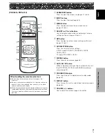
Страница 11: ...utton Press to open and close the on screen menu pages 20 to 41 4 ADJUST 5 3 2 buttons Use to navigate menu screens and to adjust various settings on the unit pages 20 to 41 5 SET button Press to adjust or enter various settings on the unit pages 20 to 41 6 AV SELECTION button Press to switch to Picture settings VIDEO mode DYNAMIC STANDARD MOVIE GAME USER PC mode STANDARD USER 7 MUTING button Pres...

Страница 12: ...remote control unit When operating the remote control unit point it at the remote sensor Î located on the front panel of the main unit The remote control unit is operable up to 7 m 23 feet from the unit and within a 30 angle on each side of the sensor Inserting the batteries in the remote control unit CAUTION Insert batteries so that the plus and minus sides are aligned according to the markings i...

Страница 13: ...onent pages 13 to 14 4 AUDIO INPUT1 RCA pin jack Use to obtain sound when INPUT1 is selected Connect this jack to the audio output connector of the device connected to INPUT1 to this unit page 17 Note The left audio channel L jack is not compatible with monaural input sources Connection Panel Illustration depicts PDP 5004 PDP 5014 PDP 4304 and PDP 4314 models 5 AUDIO INPUT2 RCA Pin jacks Use to ob...

Страница 14: ... video deck video camera laser disc player or DVD recorder page 15 VIDEO OUT INPUT4 RCA Pin jack Use the VIDEO OUT INPUT4 jack to output the video signal to an external monitor or other component Note The video signal will not be output from the VIDEO OUT INPUT4 jack when the main power of this display is off or in standby mode page 15 AUDIO R L INPUT4 RCA Pin jacks Use to obtain sound when INPUT4...

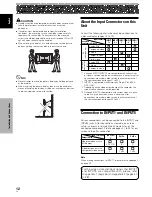
Страница 15: ...de view diagram below As this unit is constructed with glass be sure to install it on a flat unwarped surface CAUTION To avoid malfunction overheating of this unit and possible fire hazard make sure that the vents on the main unit are not blocked when installing Also as hot air is expelled from the air vents be careful of deterioration and dirt build up on rear surface wall etc CAUTION Please be s...

Страница 16: ...nals setup using the on screen menu is necessary after connections are made in order match the characteristics of the source component pages 23 to 24 INPUT 4 INPUT 3 3 3 Input Connector INPUT 1 1 INPUT 2 4 Analog RGB Component video S video Composite video Digital video Personal computer PC AV component Connected component and signals Analog RGB S video Composite video 2 INPUT 5 1 For the screen s...

Страница 17: ...nit is designed to support component video signals with standard stable signal levels and sync signals As a result some image disruption may be generated during use of various special trick play functions on video components Connection of G ON SYNC analog RGB source Make G ON SYNC connections for a component with output that has the synchronization signal layered on top of the green signal When co...

Страница 18: ...e sure to make sure that the personal computer s power and display s main power is off For the PC input signals and screen sizes that the display is compatible with please refer to the plasma display s Operating Instructions When connecting to ANALOG RGB IN INPUT1 ANALOG RGB IN D Sub AUDIO INPUT1 INPUT1 R L Connect the cable corresponding to the shape of the input terminal on the display and the p...

Страница 19: ...to be used with a personal computer See appendix 1 page 46 for information regarding signal and display formats supported by INPUT2 HDMI the HDMI logo and High Definition Multimedia Interface are trademarks or registered trademarks of HDMI Licensing LLC AV component AV component To a monitor or a recording device AUDIO R L HDMI INPUT2 AV component with a digital video output Connection to INPUT3 C...

Страница 20: ...al supplied with the DTV set top box The set top box output signals that this display is compatible with are as follows Video signal type Video signal format Video signal INPUT1 Jacks where connection is possible INPUT4 INPUT3 INPUT2 HDTV SDTV 1080i 1125i 720p 750p 480i 525i 480p 525p Component RGB Digital Composite S Video Component RGB Digital Component RGB Digital INPUT5 ...

Страница 21: ...ures five audio inputs The following chart shows the video inputs and the corresponding audio input terminals INPUT1 INPUT2 INPUT3 INPUT4 INPUT5 Audio input jacks Sound output Pin jacks L R Pin jacks L R Pin jacks L R Pin jacks L R Pin jacks L R Sound of the selected video input is output from the SPEAKER L R terminals Video input Twist exposed wire strands together Push tab to the open position a...

Страница 22: ... audio line for the component connected to INPUT5 can be connected to the AUDIO R L INPUT5 pin jacks Sound is output from the SPEAKER L R terminals according to the video input selection Power Cord Connection Connect the power cord after all component connections have been completed 1 Connect the power cord to this unit 2 Plug the power cord into a power outlet CAUTION Use only the power cord prov...

Страница 23: ...2 into the back of 1 to fix the clamp Speed clamps are designed to be difficult to undo once in place Please attach carefully To attach the speed clamps to the display Connect the speed clamps using the 6 holes marked with below depending on the situation To remove speed clamps Using pliers twist the clamp 90 and pull it outward In some cases the clamp may have deteriorated over time and may be da...

Страница 24: ... ON COLOR TEMP MID PICTURE RESET ENTER SET EXIT MENU 0 0 0 0 0 4 Use the 2 3 buttons to select OPTION STANDARD INPUT1 ENERGY SAVE POWER MANAGEMENT OFF AUTO POWER OFF DISABLE ORBITER OFF MASK CONTROL ON STANDARD LANGUAGE ENGLISH ENTER SET EXIT MENU PICTURE SCREEN SETUP OPTION 5 Use the 5 buttons to select LANGUAGE then press the SET button SET SET EXIT MENU ENGLISH LANGUAGE 6 Use the 2 3 buttons to...

Страница 25: ...to display the menu screen STANDARD INPUT1 PICTURE SCREEN SETUP OPTION CONTRAST BRIGHTNESS COLOR TINT SHARPNESS MPEG NR DNR CTI ON MID ON COLOR TEMP MID PICTURE RESET ENTER SET EXIT MENU 0 0 0 0 0 3 Use the 2 3 buttons to select SETUP STANDARD INPUT1 PICTURE SCREEN SETUP OPTION PURECINEMA CLAMP POSITION SIGNAL FORMAT COLOR DECODING HDMI INPUT COMPONENT 480p AUTO OFF ENTER SET EXIT MENU 4 Use the 5...

Страница 26: ...ress the SET button This completes COLOR DECODING setting and returns you to the display shown in Step 7 10 After completing settings press the MENU button to return to the normal display CLAMP POSITION setup INPUT1 5 Depending on the signal analog RGB signals may result in the screen image appearing with a whitish or greenish cast In such cases set CLAMP POSITION to LOCKED Normally leave this set...

Страница 27: ...N SETUP OPTION CONTRAST BRIGHTNESS COLOR TINT SHARPNESS MPEG NR DNR CTI ON MID ON PICTURE RESET ENTER SET EXIT MENU 0 0 0 COLOR TEMP MID 0 0 2 Use the 2 3 buttons to select SET UP STANDARD INPUT2 PICTURE SCREEN SETUP OPTION PURECINEMA CLAMP POSITION SIGNAL FORMAT COLOR DECODING HDMI INPUT OFF ENTER SET EXIT MENU 3 Use the 5 buttons to select HDMI INPUT then press the SET button STANDARD INPUT2 PIC...

Страница 28: ...5 buttons to select HDMI INPUT then press the SET button STANDARD INPUT2 PICTURE SCREEN SETUP OPTION PURECINEMA CLAMP POSITION SIGNAL FORMAT COLOR DECODING HDMI INPUT OFF ENTER SET EXIT MENU 4 Use the 5 buttons to select AUDIO HDMI INPUT PICTURE SELECT AUDIO SET SET EXIT MENU AUTO AUTO 5 Use the 2 3 buttons to select AUDIO setting The unit has been factory set at the AUTO setting Each time you pre...

Страница 29: ...ol unit or the display to select the input Input changes each time the display s INPUT button is pressed as follows When the menu screen is displayed changing the signal input will cause the menu screen to turn off If the input computer signal is not supported by the display the following message will be displayed FULL 8 8 5 H z f V 8 6 7 k H z 1 1 5 2 x 8 6 4 D SUB f H CAUTION UNSUPPORTED SIGNAL ...

Страница 30: ... Press the MUTING button on the remote control unit Press the MUTING button again to restore the sound Pressing VOLUME also quits muting Confirming Current Status DISPLAY Remote control unit Press the DISPLAY button The currently selected input AV selection screen size and refresh rates will be displayed for about 3 seconds D O T B Y D O T 0 6 0 D S U B 1 0 2 4 X 7 6 8 k H z fV 4 4 8 H z fH INPUT1...

Страница 31: ... INPUT1 The screen modes you can select differ depending on the input signal For details please refer to the Supported Video Signal chart on page 46 or the Supported PC Signal chart on pages 47 to 48 Notes When the WIDE ZOOM or FULL setting is used to display a non wide screen 4 3 picture fully on a wide screen a portion of the picture may be cut off or appear deformed Be aware that when the displ...

Страница 32: ...n A 480 lines 768 lines 640 dots 1280 dots 768 lines 480 lines Note When viewing at aspect ratio 4 3 continuously for numerous hours or for repeated short periods of time each day some after image may be burned into the screen To avoid such burning of after images in the screen use aspect ratios other than 4 3 whenever possible unless necessary to avoid infringement of copyright Multiscreen Displa...

Страница 33: ...s the DISPLAY button If the DISPLAY button is pressed while in multiscreen mode the main screen and sub screen will each be displayed with its currently selected input Notes When using the plasma display in a profit making activity or when exhibiting images publicly using the screen size function to compress or stretch the image may result in infringement of the copyrights of the image owners If t...

Страница 34: ...uch as during menu screen display and when there is no signal input Operation Setting AV SELECTION To let you enjoy the best picture you can select between 5 settings during video signal input and 2 during PC signal input 1 Press the AV SELECTION button The current AV SELECTION mode is displayed at the top right of the screen INPUT1 STANDARD 2 Press the AV SELECTION button again in the AV SELECTIO...

Страница 35: ...d you return to the display shown in step 3 6 After completing settings press the MENU button to return to the normal display Adjustment and setting items during video signal input Decrease Increase CONTRAST Contrast becomes weaker Contrast becomes stronger BRIGHTNESS Picture becomes darker Picture becomes brighter COLOR Colors become weaker Colors become stronger TINT Skin tones become purplish S...

Страница 36: ... unit 2 Press the MENU button to display the menu STANDARD INPUT1 PICTURE SCREEN SETUP OPTION CONTRAST BRIGHTNESS COLOR TINT SHARPNESS MPEG NR DNR CTI ON MID ON COLOR TEMP MID PICTURE RESET ENTER SET EXIT MENU 0 0 0 0 0 3 Use the 5 buttons to select PICTURE RESET then press the SET button STANDARD INPUT1 PICTURE SCREEN SETUP OPTION CONTRAST BRIGHTNESS COLOR TINT SHARPNESS MPEG NR DNR CTI PICTURE R...

Страница 37: ...O SET UP Notes This setting is supported only when a computer signal is connected to INPUT1 Perform this adjustment individually for each signal type Optimum settings may not be possible for low luminance and certain other signals In such cases use the adjustment methods explained on the this page Adjusting Screen POSITION CLOCK and PHASE Manual Adjust If you run AUTO SET UP POSITION CLOCK and PHA...

Страница 38: ...izontal direction H and the 5 buttons control movement in the Vertical direction V SET SET EXIT MENU POSITION SET SET EXIT MENU 0 0 H V Use the 2 3 buttons for the adjustments of CLOCK and PHASE SET SET EXIT MENU 0 CLOCK 5 Press the SET button Pressing the SET button writes the value into the memory and returns the display to the step 3 screen 6 After completing settings press the MENU button to r...

Страница 39: ...zontal H option may require readjustment If the adjustment items in the SCREEN mode are adjusted excessively the picture may not be displayed properly During video signal input and PC signal input INPUT1 adjustment values are saved separately To reset SCREEN mode settings to the default 1 In step 3 in the previous procedure use the 5 buttons to select SCREEN RESET then press the SET button SET SET...

Страница 40: ...p AUTO OFF ENTER SET EXIT MENU 4 Use the 2 3 buttons to select the desired PURECINEMA mode SET SET EXIT MENU OFF PURECINEMA Status at the time of factory default setting During 480p and 720p signal input OFF During input of a video signal other than those above STANDARD Each time the button is pressed the screen mode setting changes as shown PDP 5004 PDP 4304 OFF PURECINEMA function is disabled ST...

Страница 41: ...ioration MENU 5 SET 2 3 Remote control unit Other Operations 3 OFF 2 3 STANDARD 2 1 Press the MENU button to display the menu screen STANDARD INPUT1 PICTURE SCREEN SETUP OPTION CONTRAST BRIGHTNESS COLOR TINT SHARPNESS MPEG NR DNR CTI ON MID ON COLOR TEMP MID PICTURE RESET ENTER SET EXIT MENU 0 0 0 0 0 2 Use the 2 3 buttons to select OPTION STANDARD INPUT1 ENERGY SAVE POWER MANAGEMENT OFF AUTO POWE...

Страница 42: ... less than that used in STANDARD mode MODE2 Brightness is controlled in accordance with input signal but power consumption is less than that used in MODE1 MODE3 Brightness is set at fixed level regardless of input signal level Effective at reducing screen aging due to burned lag images etc 5 Press the SET button ENERGY SAVE is set and you return to the display shown in step 3 6 After completing se...

Страница 43: ...ed for 8 minutes or more a warning message will be displayed for 30 seconds after which the unit s power will switch to power off mode 6 After completing settings press the MENU button to return to the normal display To return to operating mode To return to normal operation from the POWER MANAGEMENT function s standby mode either operate your computer or press the STANDBY ON button on this unit or...

Страница 44: ...n to the display shown in step 3 6 After completing settings press the MENU button to return to the normal display Note The ORBITER setting affects all input sources Other Operations Side Mask Position MASK CONTROL When screen size is set to DOT BY DOT or 4 3 or when using multiscreen display the position of all elements change slightly each time the power is turned on in order to alleviate burnin...

Страница 45: ...TURE SCREEN SETUP OPTION LANGUAGE 4 Press the 2 3 buttons to activate the setting SET SET EXIT MENU ON MASK CONTROL The factory default setting is ON Each time the button is pressed the setting alternates as follows 5 Press the SET button MASK CONTROL is set and you return to the display shown in step 3 6 After completing settings press the MENU button to return to the normal display Note The MASK...

Страница 46: ...st seem to be an malfunction may be remedied with a quick check Please check to see a warning is displayed on the screen If displayed refer to the table below and check the mode If there is no display check to see the problem is listed on page 43 The problem may also be caused by something other than this unit so please also check the other components being used such as a video deck If the problem...

Страница 47: ... after ambient temperature exceeds 35 C 95 F differs depending on installation conditions Not a malfunction Fan speed changes automatically in accordance with ambient conditions Not a malfunction Problem Possible Solution General problems No power Unit cannot be operated Remote control does not operate Picture is cut off Strange color light color or dark or color misalignment Power is suddenly tur...

Страница 48: ... pixels may fail to light or may light erratically This is an inevitable by product of the manufacturing process and not a malfunction Concerning infrared light In principle the plasma display radiates infrared light Depending on the environment in which the monitor is installed and used infrared remote control units for other nearby appliances may fail to operate properly or noise may be heard in...

Страница 49: ...ini D sub 15 pin socket connector RGB signal G ON SYNC compatible RGB 0 7 Vp p 75 Ω no sync HD VS VD TTL level positive and negative polarity 2 2 kΩ G ON SYNC 1 Vp p 75 Ω negative sync Compatible with Microsoft Plug Play VESA DDC1 2B Component video signal Y 1 Vp p 75 Ω negative sync CB PB CR PR 0 7 Vp p color100 75 Ω INPUT2 Input HDMI Digital signal 3 3V T M D S 50 Ω INPUT3 Input S jack Mini DIN ...

Страница 50: ...patibility table INPUT1 INPUT5 Not available 15 734 31 5 33 75 45 0 Vertical fV Hz Horizontal fH kHz Signal format 4 3 FULL ZOOM CINEMA Remarks 60 59 94 Component RGB Component RGB Component RGB Component RGB Screen size 480i 525i SDTV 480p 525p SDTV 1080i 1125i HDTV 720p 750p HDTV Refresh rate WIDE Digital signal compatibility table INPUT2 Not available 720x480i 720x480p 1280x720p 1920x1080i Vert...

Страница 51: ...Hz 75Hz 74 9Hz 85Hz 60Hz 56Hz 60Hz 70Hz 640x400 720x400 640x480 848x480 800x600 832x624 1024x768 1280x720 1280x768 NEC PC 9800 NEC PC 9800 Apple Macintosh 13 1072x600 Apple Macintosh 16 1376 x 768 indicates Apple Macintosh 19 1280x768 1280x768 1280x768 1280x768 1280x768 1280x768 1280x768 1280x768 640x480 848x480 800x600 832x624 1024x768 1280x720 1280x768 24 8kHz 31 5kHz 37 9kHz 31 5kHz 35 0kHz 37 ...

Страница 52: ...024x768 24 8kHz 31 5kHz 37 9kHz 31 5kHz 35 0kHz 37 9kHz 37 5kHz 43 3kHz 31 0kHz 35 2kHz 37 9kHz 48 1kHz 46 9kHz 53 7kHz 49 7kHz 48 4kHz 56 5kHz 60 0kHz 60 2kHz 68 7kHz 44 7kHz 45 1kHz 47 8kHz 56 1kHz 768x768 768x768 768x768 768x768 640x400 720x400 640x480 848x480 800x600 832x624 1024x768 1280x720 1280x768 NEC PC 9800 NEC PC 9800 Apple Macintosh 13 1072x600 Apple Macintosh 16 1376 x 768 indicates A...

Страница 53: ...gnals separately Because they are not combined as in the composite video signal the high quality of both signals can be retained Component video signal General term for video signal format composed of the Y CBCR Y PBPR and Y B Y R Y luminance signal color signal The component video signal is sometimes simply called the color difference signal G ON SYNC This indicates a video signal in the form of ...

Страница 54: ...garantie ci jointe et gardez la dans un lieu sûr pour la consulter ultérieurement Cet appareil numérique de la classe B est conforme à la norme NMB 003 du Canada Cet appareil a été testé est trouvé conforme avec les limites des appareils numériques de classe B conformément à l article 15 du règlement FCC Ces limites sont conçues pour offrir une protection raisonnable contre les interférences nuisi...

Страница 55: ...e 27 Réglage du niveau d écoute 28 Interruption des sons 28 Vérification des réglages actuels 28 Adoption du format d image 29 Affichage de plusieurs images 31 Paramétrage de AV SELECTION 32 Réglage de l image et de son affichage 33 Réglage image 33 Rétablissement des valeurs initiales des paramètres d image 34 Réglage de POSITION HORLOGE et PHASE Réglage automatique 35 Réglage de POSITION HORLOGE...

Страница 56: ... tenir compte des appareils associés et des goûts personnels Apple et Macintosh sont des marques déposées par Apple Computer Inc Microsoft est une marque déposée par Microsoft Corporation NEC et PC 9800 sont des marques de commerce de NEC Corporation VESA et DDC sont des marques déposées par Video Electronics Standards Association Power Management et Sun Microsystems sont des marques déposes par S...

Страница 57: ...r afficher la page de menu STANDARD ENTRÉE1 IMAGE ÉCRAN SETUP OPTION CONTRASTE LUMINOSITÉ COULEUR TEINTE NETTETÉ MPEG NR DNR CTI MARCHE MOYEN MARCHE RÉINIT IMAGE ENTRÉE SET SORTIE MENU 0 0 0 TEMP COULEUR MOYEN 0 0 3 Utilisez les touches 5 pour sélectionner le paramètre puis appuyez sur la touche SET STANDARD ENTRÉE1 IMAGE ÉCRAN SETUP OPTION CONTRASTE LUMINOSITÉ COULEUR TEINTE NETTETÉ MPEG NR DNR C...

Страница 58: ...oires suivants vous ont été fournis 1 Cordon d alimentation 2 Boîtier de télécommande 3 Piles AA R6 x 2 4 Chiffon de nettoyage pour la face avant 5 Colliers rapides x 2 6 Colliers à œil x 2 Avant de commencer Mode d emploi Carte de garantie L illustration représente les modèles PDP 5004 et PDP 4304 ...

Страница 59: ...04 utilisent des méthodes différentes de fixation de leurs poignées mais l utilisation de ces poignées est la même Panneau de commande de l appareil 5 Touche STANDBY ON Appuyez sur cette touche pour mettre l écran en service ou en veille page 27 6 Touche INPUT Appuyez sur cette touche pour sélectionner l entrée page 27 7 Touche SCREEN SIZE Appuyez sur cette touche pour sélectionner le format de l ...

Страница 60: ...s 21 à 43 6 Touche AV SELECTION Appuyez sur cette touche pour accéder aux réglages image En mode VIDEO DYNAMIQUE STANDARD CINÉMA JEU UTILISATEUR En mode PC STANDARD UTILISATEUR 7 Touche SUB INPUT Tandis que plusieurs images sont affichées sur l écran utilisez cette touche pour sélectionner l entrée associée à l image secondaire page 31 8 Touche SPLIT Appuyez sur cette touche pour afficher plusieur...

Страница 61: ...3 2 Utilisez ces touches pour déplacer le curseur sur les menus affichés afin de sélectionner un paramètre et pour modifier la valeur du paramètre pages 21 à 43 5 Touche SET Appuyez sur cette touche pour choisir une valeur de paramètre et pour la valider pages 21 à 43 6 Touche AV SELECTION Appuyez sur cette touche pour accéder aux réglages image En mode VIDEO DYNAMIQUE STANDARD CINÉMA JEU UTILISAT...

Страница 62: ...tier de télécommande pour agir sur l appareil vous devez le diriger vers le capteur de télécommande Î qui se trouve sur la face avant La portée du boîtier de télécommande est de l ordre de 7 m 23 pieds l angle par rapport au capteur de télécommande ne doit pas dépasser 30 Mise en place des piles dans le boîtier de télécommande ATTENTION Introduisez les piles de manière que les pôles et soient en r...

Страница 63: ... D sub 15 broches Pour le raccordement à un appareil pourvu d une prise de sortie RGB par exemple un ordinateur personnel ou un décodeur RGB ou encore pour le raccordement d un appareil possédant des prises de sortie de composantes comme c est le cas d un graveur de DVD Veillez à ce que la liaison soit compatible avec le format du signal provenant de l appareil associé pages 13 à 14 Panneau de rac...

Страница 64: ...ecteur de LaserDisc ou d un graveur de DVD page 15 AUDIO R L INPUT3 fiches Cinch RCA S utilise pour obtenir le son quand ENTRÉE3 est sélectionnée Raccordez les prises de sortie audio de l appareil relié à la prise INPUT3 page 18 VIDEO IN INPUT4 fiches Cinch RCA Pour le raccordement à la prise de sortie vidéo composite d un magnétoscope d une caméra vidéo d un lecteur de LaserDisc ou d un graveur d...

Страница 65: ...t à droite et à gauche de l axe vertical Dans le cas des perçage a utilisez des boulons dont la longueur est telle qu ils pénètrent dans l écran à plasma de 12 mm au moins et de 18 mm au plus Reportez vous à la vue de côté ci dessous L écran à plasma est muni d une vitre qui interdit sa pose sur une surface qui n est pas plane ATTENTION Pour éviter toute anomalie de fonctionnement une surchauffe d...

Страница 66: ... en matière de formats d image et de signaux d entrée veuillez vous reporter à l annexe 1 page 48 et à l annexe 2 pages 49 et 50 INPUT 4 INPUT 3 3 3 Prise d entrée INPUT 1 1 INPUT 2 4 RVB analogique Composante vidéo S vidéo Vidéo composite Vidéo numérique RVB analogique S vidéo Vidéo composite Ordinateur personnel PC Appareil audiovisuel Appareil et signaux concernés 2 INPUT 5 1 Prise INPUT5 Sorti...

Страница 67: ...gnal Y sur la prise Y le signal CB PB sur la prise CB PB et le signal CR PR sur la prise CR PR Remarque Cet appareil a été conçu pour fonctionner à partir de composantes vidéo et de signaux de synchronisation présentant un niveau stable et standard En conséquence des perturbations peuvent apparaître au niveau de l image en présence de signaux de lecture inusités associés aux composantes vidéo Racc...

Страница 68: ...onnel La manière d effectuer le raccordement dépend du type de l ordinateur Avant de réaliser les raccordements lisez attentivement le mode d emploi de l ordinateur Prenez soin de vous assurer que l ordinateur personnel et son écran sont hors tension avant d effectuer quelque branchement que ce soit Pour connaître la compatibilité de cet appareil en matière de formats d image et de signaux d entré...

Страница 69: ...câble convertisseur DVI HDMI pour réaliser la liaison Cette prise n est pas prévue pour être utilisée avec un ordinateur personnel Reportez vous à l annexe 1 page 48 pour de plus amples détails concernant les signaux et les formats d image qui sont pris en compte par ENTRÉE2 AUDIO R L HDMI INPUT2 Appareil audiovisuel possédant une sortie vidéo numérique Raccordement à INPUT3 Utilisez cette prise p...

Страница 70: ...viseur numérique et le décodeur Les signaux de sortie du décodeur compatibles avec cet écran figurent dans le tableau qui suit Installation et raccordements Prises qui peuvent être utilisées Type de signal vidéo Format du signal vidéo Signal vidéo INPUT1 INPUT4 INPUT3 INPUT2 HDTV SDTV 1080i 1125i 720p 750p 480i 525i 480p 525p Composantes RVB Numérique Vidéo composite S vidéo Composantes RVB Numéri...

Страница 71: ...et appareil est équipé de 5 entrées audio Le tableau qui suit donne la liste des entrées vidéo et des entrées audio qui leur correspondent INPUT1 INPUT2 INPUT3 INPUT4 INPUT5 Prises d entrée audio Sortie son Fiches G D Fiches G D Fiches G D Fiches G D Fiches G D Les sons provenant de l appareil vidéo sélectionné sont présents en sortie sur les prises SPEAKER L R Entrée vidéo Torsadez les brins mis ...

Страница 72: ...l relié à INPUT4 R L INPUT4 AUDIO La liaison audio pour l appareil relié à l entrée INPUT4 peut être réalisée par le truchement des prises AUDIO R L INPUT4 Les sons sont appliqués sur les prises SPEAKER L R en fonction de la source vidéo sélectionnée Installation et raccordements Raccordement audio pour l appareil relié à INPUT5 R L INPUT5 AUDIO La liaison audio pour l appareil relié à l entrée IN...

Страница 73: ...ez que le cordon d alimentation fourni Par souci de sécurité le système d écran plasma est doté d un cordon d alimentation à 3 conducteurs Veillez à brancher la fiche du cordon d alimentation sur une prise secteur à 3 broches convenablement reliée à la terre Si vous utilisez un adaptateur assurez vous qu il est muni d une borne de masse et reliez celle ci à la terre NON N alimentez pas l appareil ...

Страница 74: ...rer la fermeture du collier Les colliers rapides sont conçus pour être difficiles à déposer une fois qu ils sont en place et fermés Effectuez leur pose avec soin Fixation des colliers rapides à l écran Fixez les colliers rapides dans les 6 perçages repérés par sur l illustration ci dessous cela en fonction du cheminement prévu pour les câbles Pour déposer les colliers rapides Utilisez une paire de...

Страница 75: ...TEMP MID PICTURE RESET ENTER SET EXIT MENU 0 0 0 0 0 4 Utilisez les touches 2 3 pour sélectionner OPTION STANDARD INPUT1 ENERGY SAVE POWER MANAGEMENT OFF AUTO POWER OFF DISABLE ORBITER OFF MASK CONTROL ON STANDARD LANGUAGE ENGLISH ENTER SET EXIT MENU PICTURE SCREEN SETUP OPTION 5 Utilisez les touches 5 pour sélectionner LANGUAGE puis appuyez sur la touche SET SET SET EXIT MENU ENGLISH LANGUAGE 6 U...

Страница 76: ...ovient d un ordinateur il en est de même lorsque la fonction TYPE DE SIGNAL a été utilisée pour sélectionner un signal autre que 480p ou 720p Effectuez les paramétrages de DÉCODAGE COULEUR séparément pour ENTRÉE1 ou ENTRÉE5 Le paramétrage de TYPE DE SIGNAL n est possible que lorsque ENTRÉE1 est sélectionnée 1 Sélectionnez ENTRÉE1 ou ENTRÉE5 2 Appuyez sur la touche MENU pour afficher la page de men...

Страница 77: ...n mémoire puis la page affichée au cours de l opération 4 est rétablie 7 Lorsqu un appareil autre qu un ordinateur est relié utilisez les touches 5 pour sélectionner DÉCODAGE COULEUR puis appuyez sur la touche SET ENTRÉE1 ou ENTRÉE5 STANDARD ENTRÉE1 IMAGE ÉCRAN SETUP OPTION PURECINEMA POSITION CLAMP TYPE DE SIGNAL DÉCODAGE COULEUR ENTRÉE HDMI COMPOSANTE 480p AUTO ARRÊT ENTRÉE SET SORTIE MENU 8 Uti...

Страница 78: ...ION CLAMP puis appuyez sur la touche SET STANDARD ENTRÉE1 IMAGE ÉCRAN SETUP OPTION PURECINEMA POSITION CLAMP TYPE DE SIGNAL DÉCODAGE COULEUR ENTRÉE HDMI RVB 480p AUTO ARRÊT ENTRÉE SET SORTIE MENU 4 Utilisez les touches 2 3 pour sélectionner VERROUILLÉ VALIDER SET SORTIE MENU VERROUILLÉ POSITION CLAMP La valeur par défaut est AUTO Chaque pression sur les touches 2 3 buttons modifie le réglage comme...

Страница 79: ...ODAGE COULEUR ENTRÉE HDMI ARRÊT ENTRÉE SET SORTIE MENU 4 Utilisez les touches 5 pour sélectionner SÉLECTION D IMAGE ENTRÉE HDMI SÉLECTION D IMAGE AUDIO VALIDER SET SORTIE MENU AUTO AUTO 5 Utilisez les touches 2 3 pour sélectionner le paramètre SÉLECTION D IMAGE Le réglage adopté en usine pour l appareil est AUTO Chaque pression sur les touches 2 3 modifie le réglage comme suit AUTO Le type des sig...

Страница 80: ...SIGNAL DÉCODAGE COULEUR ENTRÉE HDMI ARRÊT ENTRÉE SET SORTIE MENU 4 Utilisez les touches 5 pour sélectionner AUDIO ENTRÉE HDMI SÉLECTION D IMAGE AUDIO VALIDER SET SORTIE MENU AUTO AUTO 5 Utilisez les touches 2 3 pour sélectionner le paramètre AUDIO Le réglage adopté en usine pour l appareil est AUTO Chaque pression sur les touches 2 3 modifie le réglage comme suit AUTO Le type des signaux d entrée ...

Страница 81: ...e INPUT de l écran change l entrée sélectionnée comme suit Lorsque la page de menu est affichée tout changement d entrée provoque l effacement de la page de menu Si le signal provenant de l ordinateur n est pas pris en compte par l écran le message suivant s affiche PLEIN ÉCRAN 8 8 5 H z f V 8 6 7 k H z 1 1 5 2 x 8 6 4 D SUB f H ATTENTION SIGNAL NON RECONNU ENTRÉE1 STANDARD ENTRÉE1 STANDARD PLEIN ...

Страница 82: ...raîchissement adopté sont affichés pendant environ 3 secondes POINT PAR POINT 0 6 0 D S U B 1 0 2 4 X 7 6 8 k H z fV 4 4 8 H z fH ENTRÉE1 STANDARD Remarque La valeur affichée pour le taux de rafraîchissement peut être légèrement différente de la valeur réelle Réglage du niveau d écoute Appuyez sur les touchesVOLUME Appuyez sur la touche ou sur la touche pour diminuer ou augmenter le niveau sonore ...

Страница 83: ...mats d image sélectionnables diffèrent en fonction du signal d entrée Pour plus de détails veuillez vous reporter au tableau de la page 48 Signaux vidéo pris en compte Dans le cas où le signal d entrée provient d un ordinateur personnel ENTRÉE1 Le format d image que vous pouvez sélectionner dépend de la nature du signal d entrée Pour de plus amples détails concernant cette question veuillez vous r...

Страница 84: ...sion CINÉMA 768 lignes 480 lignes 1280 points 640 points PDP 4304 PDP 4314 Le PDP 4304 et PDP 4314 sont réalisé avec des éléments horizontaux oblongs ce qui se traduit par une image affichée plus oblongue que l image originale que contient le signal d entrée A L illustration montre le cas d une entrée 640 x 480 2 4 3 L image remplit l écran autant qu il est possible sans pour autant que le format ...

Страница 85: ...econdaire et vice versa Pour changer la position de l image secondaire quand le mode PinP est adopté Appuyez sur la touche PIP SHIFT du boîtier de télécommande Chaque pression sur cette touche change la position de l image secondaire comme suit 3 Coin inférieur droit 3 Coin supérieur droit Coin inférieur gauche 2 Coin supérieur gauche 2 Affichage de plusieurs images PDP 5004 PDP 4304 seulement L é...

Страница 86: ...pas choisir le mode AV SELECTION 3 DYNAMIQUE 3 STANDARD UTILISATEUR 2 JEU 2 CINÉMA 2 3 STANDARD UTILISATEUR 2 Pour afficher l image de l entrée actuellement sélectionnée Appuyez sur la touche DISPLAY Si vous appuyez sur la touche DISPLAY alors que l écran peut afficher plusieurs images l image principale et l image secondaire de chaque entrée sélectionnée s affichent Remarques Lorsque l écran à pl...

Страница 87: ...TEMP COULEUR MOYEN 0 0 4 Utilisez les touches 2 3 pour régler le paramètre d image à la valeur convenable SR MODE VALIDER SET SORTIE MENU ON 0 CONTRASTE 5 Appuyez sur la touche SET La valeur du paramètre est sauvegardée et la page affichée au cours de l opération 3 est rétablie 6 Lorsque le réglage est achevé appuyez sur la touche MENU pour rétablir la page standard Réglages des paramètres pour un...

Страница 88: ... ordinateur personnel Diminution Augmentation CONTRASTE Le contraste devient plus Le contraste devient plus faible fort LUMINOSITÉ L image devient plus sombre L image devient plus lumineuse Rétablissement des valeurs initiales des paramètres d image Pour rétablir les valeurs des paramètres au moment de la sortie d usine procédez comme suit Remarque Ce réglage n est pas disponible si vous adoptez l...

Страница 89: ...que Tandis que le signal appliqué à l entrée provient d un ordinateur personnel vous pouvez en appuyant sur la touche AUTO SET UP du boîtier de télécommande ou du panneau de commande de l écran obtenir le réglage optimal de position de l image et celui de l horloge en tenant compte du signal fournie par la source AUTO SET UP AUTO SET UP Boîtier de télécommande Panneau de commande de l écran à plas...

Страница 90: ...0 0 Réglage de l image et de son affichage Menu dans le cas d un signal provenant d un appareil vidéo et appliqué via INPUT1 ou INPUT5 STANDARD ENTRÉE1 IMAGE ÉCRAN SETUP OPTION POSITION RÉINIT ÉCRAN ENTRÉE SET SORTIE MENU 0 0 3 Utilisez les touches 5 pour sélectionner le paramètre puis appuyez sur la touche SET STANDARD ENTRÉE1 IMAGE ÉCRAN SETUP OPTION POSITION HORLOGE PHASE RÉINIT ÉCRAN ENTRÉE SE...

Страница 91: ...e vidéo POSITION H Agit sur la position horizontale de l image V Agit sur la position verticale de l image Remarques Le réglage de HORLOGE et de PHASE est possible dans le cas d un signal provenant d un ordinateur personnel et appliqué via INPUT1 Après une modification de la valeur de HORLOGE celle de POSITION peut exiger un nouveau réglage dans le sens horizontal H Si les valeurs retenues pour le...

Страница 92: ...RECINEMA désiré VALIDER SET SORTIE MENU ARRÊT PURECINEMA Valeur de réglage par défaut à la fabrique Lors de l entrée d un signal 480p ou 720p ARRÊT Lors de l entrée d un signal vidéo autre que ceux ci dessus STANDARD Chaque pression sur cette touche provoque la sélection d un autre mode comme suit PDP 5004 PDP 4304 ARRÊT La fonction PURECINEMA n est pas en service STANDARD Lors de la lecture de DV...

Страница 93: ...er 1 Appuyez sur la touche MENU pour afficher la page de menu STANDARD ENTRÉE1 IMAGE ÉCRAN SETUP OPTION CONTRASTE LUMINOSITÉ COULEUR TEINTE NETTETÉ MPEG NR DNR CTI MARCHE MOYEN MARCHE RÉINIT IMAGE ENTRÉE SET SORTIE MENU 0 0 0 TEMP COULEUR MOYEN 0 0 2 Utilisez les touches 2 3 pour sélectionner OPTION STANDARD ENTRÉE1 ÉCONOM D ÉNERGIE GESTION D ALIM ARRÊT ARRÊT AUTOMATIQUE DÉSACTIVÉ ORBITER ARRÊT CO...

Страница 94: ... consommation d énergie est inférieure à celle du mode MODE1 MODE3 La luminosité est fixe et indépendante du signal d entrée Cette valeur réduit le vieillissement de l écran dû aux phénomènes de brûlage etc 5 Appuyez sur la touche SET La fonction ÉCONOM D ÉNERGIE est mise en service puis la page affichée au cours de l opération 3 est rétablie 6 Lorsque le réglage est achevé appuyez sur la touche M...

Страница 95: ...sse en mode normal de fonctionnement 1 Sauf si le signal est de type G ON SYNC ou composite ARRÊT AUTOMATIQUE ACTIVÉ Si aucun signal de synchronisation n est détecté pendant au moins 8 minutes un message d avertissement s affiche durant 30 secondes puis l alimentation de l appareil est coupée 3 ARRÊT DÉSACTIVÉ 2 3 MARCHE ACTIVÉ 2 6 Lorsque le réglage est achevé appuyez sur la touche MENU pour réta...

Страница 96: ...NTRÉE SET SORTIE MENU 0 0 0 TEMP COULEUR MOYEN 0 0 Autres opérations 1 Appuyez sur la touche MENU pour afficher la page de menu STANDARD ENTRÉE1 IMAGE ÉCRAN SETUP OPTION CONTRASTE LUMINOSITÉ COULEUR TEINTE NETTETÉ MPEG NR DNR CTI MARCHE MOYEN MARCHE RÉINIT IMAGE ENTRÉE SET SORTIE MENU 0 0 0 TEMP COULEUR MOYEN 0 0 2 Utilisez les touches 2 3 pour sélectionner OPTION STANDARD ENTRÉE1 ÉCONOM D ÉNERGIE...

Страница 97: ...TIQUE DÉSACTIVÉ ORBITER ARRÊT CONTRÔLE MASQUE MARCHE STANDARD FRANÇAIS IMAGE ÉCRAN SETUP OPTION LANGUAGE 4 Appuyez sur les touches 2 3 pour valider le réglage VALIDER SET SORTIE MENU MARCHE CONTRÔLE MASQUE La valeur par défaut est MARCHE Chaque pression sur les touches 2 3 modifie le réglage comme suit 5 Appuyez sur la touche SET La fonction CONTRÔLE MASQUE est mise en service puis la page affiché...

Страница 98: ...peut arriver aussi que le défaut provienne d un autre élément de l installation assurez vous que ce n est pas le cas Si en dépit de ces contrôles vous n êtes pas en mesure d obtenir un fonctionnement satisfaisant consultez le revendeur Quelques mots sur l autodiagnostic Des messages peuvent apparaître au centre de l écran qui indiquent une anomalie de fonctionnement ou de raccordement Après avoir ...

Страница 99: ... atteint 35 C 95 F valeur qui dépend de l installation Cela ne traduit pas une anomalie de fonctionnement La vitesse du ventilateur varie avec les conditions ambiantes Cela ne traduit pas une anomalie de fonctionnement Incidents Actions correctives possibles Absence d alimentation L appareil refuse de fonctionner Le boîtier de télécommande ne fonctionne pas L image est tronquée Couleurs surprenant...

Страница 100: ...éclairent pas ou s éclairent de manière inopinée Cela tient à la technique de fabrication et ne traduit pas une anomalie Au sujet du rayonnement infrarouge Par principe l écran à plasma émet un rayonnement infrarouge En fonction de son environnement et de son utilisation l écran peut perturber le fonctionnement des appareils voisins qui réagissent à ce rayonnement et même se traduire par un brouil...

Страница 101: ...ositive et négative 2 2 kOhms G ON SYNC 1 0 Vcc 75 Ohms synchro négative Compatibilité Microsoft Plug Play VESA DDC1 2B Composantes du signal vidéo Y 1 Vcc 75 Ohms synchro négative CB PB CR PR 0 7 Vc c couleur 100 75 Ohms INPUT2 Entrée HDMI Signal numérique 3 3 V T M D S 50 Ohms INPUT3 Entrée Prise S Mini DIN 4 broches Signaux vidéo Y et C séparés Y 1 Vcc 75 Ohms synchro négative C 0 286 Vcc 75 Oh...

Страница 102: ...es Cordon d alimentation 1 Boîtier de télécommande 1 Piles AA R6 UM 3 2 Chiffon de nettoyage pour essuyer la face avant du panneau 1 Colliers rapides 2 Colliers à œil 2 Mode d emploi 1 Garantie 1 Les caractéristiques et la présentation peuvent être modifiées sans avis préalable Annexe 1 Tableau de compatibilité du signal vidéo INPUT1 INPUT5 Tableau de compatibilité pour les signaux numériques INPU...

Страница 103: ... 768 indique le moniteur Apple Macintosh 19 1280x768 1280x768 1280x768 1280x768 1280x768 1280x768 1280x768 1280x768 640x480 848x480 800x600 832x624 1024x768 1280x720 1280x768 24 8kHz 31 5kHz 37 9kHz 31 5kHz 35 0kHz 37 9kHz 37 5kHz 43 3kHz 31 0kHz 35 2kHz 37 9kHz 48 1kHz 46 9kHz 53 7kHz 49 7kHz 48 4kHz 56 5kHz 60 0kHz 60 2kHz 68 7kHz 44 7kHz 45 1kHz 47 8kHz 56 1kHz Remarque Dans certains cas rares ...

Страница 104: ...x768 24 8kHz 31 5kHz 37 9kHz 31 5kHz 35 0kHz 37 9kHz 37 5kHz 43 3kHz 31 0kHz 35 2kHz 37 9kHz 48 1kHz 46 9kHz 53 7kHz 49 7kHz 48 4kHz 56 5kHz 60 0kHz 60 2kHz 68 7kHz 44 7kHz 45 1kHz 47 8kHz 56 1kHz 768x768 768x768 768x768 768x768 640x400 720x400 640x480 848x480 800x600 832x624 1024x768 1280x720 1280x768 NEC PC 9800 NEC PC 9800 Apple Macintosh 13 1072x600 Apple Macintosh 16 1376 x 768 indique le mon...

Страница 105: ...e la qualité de l image Informations complémentaires Composantes vidéo C est un terme générique pour les signaux vidéo comprenant les éléments de luminance et de chrominance Y CBCR Y PBPR et Y B Y R Y On parle aussi de signaux de différence de couleur G ON SYNC La synchronisation du signal RVB est obtenue par l addition d un signal de synchronisation au signal du vert G VGA VGA est l abréviation d...

Страница 106: ...tro equipo Para impedir las interferencias electromagnéticas con aparatos eléctricos tales como radios y televisores utilice conectores y cables blindados para hacer las conexiones ADVERTENCIA El manoseo del cable de este producto o de cables asociados con los accesorios vendidos con el producto le exponen al plomo una sustancia química conocida en el Estado de California y otras entidades guberna...

Страница 107: ...operaciones 36 Ajuste del modo PURECINEMA 36 Ajustes de ahorro de energía AHORRO DE ENERGÍA 37 Apagado automático GESTION POTENCIA 38 Ajuste orbital ORBITAL 39 Posición de la máscara lateral CONTROL MASCARA 40 Información adicional 42 Limpieza 42 Localización y solución de problemas 42 Precauciones relacionadas con la utilización 44 Indicadores STANDBY y ON 44 Especificaciones 45 Apéndice 1 46 Apé...

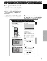
Страница 108: ...personales Visualizaciones de los menús Las visualizaciones de los menús de los ejemplos que aparecen en este manual son para los modelos PDP 5004 PDP 5014 La visualización para los modelos PDP 4304 PDP4314 se diferencia en lo siguiente Ejemplo de visualización de menú de los PDP 5004 PDP 5014 ESTÁNDAR ENTRADA1 PANT CONFG OPCION CONTRASTE BRILLO COLOR MATIZ NITIDEZ MPEG NR DNR CTI ENCENDIDO MEDIO ...

Страница 109: ...OPCION CONTRASTE BRILLO COLOR MATIZ NITIDEZ MPEG NR DNR CTI ENCENDIDO MEDIO ENCENDIDO REINIC IMAGEN INTRO SET SALIR MENU 0 0 0 TEMP COLOR MEDIO 0 0 IMAGEN 4 Utilice los botones 2 3 para ajustar la calidad de la imagen como desee SR MODE PONER SET SALIR MENU ON 0 CONTRASTE 5 Pulse el botón SET Los valores de ajuste se almacenan y la pantalla vuelve a la visualización mostrada en el paso 3 6 Cuando ...

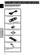
Страница 110: ...ninguno de los accesorios siguientes 1 Cable de alimentación 2 Mando a distancia 3 Pilas AA R6 x 2 4 Paño de limpieza para limpiar el panel frontal 5 Abrazaderas rápidas x 2 6 Bandas de cuentas x 2 Antes de proseguir Manual de instrucciones Garantía La ilustración muestra los modelos PDP 5004 y PDP 4304 ...

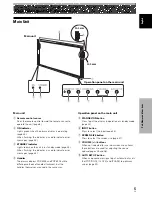
Страница 111: ...as de plasma PDP 5004 y PDP 4304 utilizan métodos diferentes de montaje de los asideros pero los asideros en sí se utilizan de la misma manera Panel de operación de la unidad principal 5 Botón STANDBY ON Púlselo para poner la pantalla en funcionamiento o en el modo de espera página 25 6 Botón INPUT Púlselo para seleccionar la entrada página 25 7 Botón SCREEN SIZE Púlselo para seleccionar el tamaño...

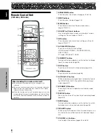
Страница 112: ...dad páginas 20 a 41 6 Botón AV SELECTION Púlselo para cambiar a los ajustes de imagen Modo VÍDEO DINÁMICO ESTÁNDAR PELÍCULA JUEGO USUARIO Modo PC ESTÁNDAR USUARIO 7 Botón SUB INPUT Durante la visualización de pantallas múltiples utilice este botón para cambiar las entradas a las pantallas secundarias página 29 8 Botón SPLIT Púlselo para cambiar a la visualización de pantallas múltiples página 29 9...

Страница 113: ...1 4 Botones ADJUST 5 3 2 Utilícelos para navegar por las pantallas de menú y para realizar los diversos ajustes en la unidad páginas 20 a 41 5 Botón SET Púlselo para ajustar o introducir diversos ajustes en la unidad páginas 20 a 41 6 Botón AV SELECTION Púlselo para cambiar a los ajustes de imagen Modo VÍDEO DINÁMICO ESTÁNDAR PELÍCULA JUEGO USUARIO Modo PC ESTÁNDAR USUARIO 7 Botón MUTING Púlselo p...

Страница 114: ...onente de esta unidad Dependiendo del lugar de instalación puede que el mando a distancia de esta unidad sufra influencias de rayos infrarrojos descargados desde la pantalla de plasma dificultando la recepción de sus rayos o limitando su distancia de funcionamiento La intensidad de los rayos infrarrojos descargados desde la pantalla difiere de acuerdo con la imagen visualizada Colocación de las pi...

Страница 115: ... configuración de fábrica 3 ANALOG RGB IN INPUT1 mini D sub de 15 clavijas Para conectar componentes equipados con tomas de salida RGB como una computadora personal o un decodificador RGB externo o componentes equipados con tomas de salida componente como una grabadora DVD Asegúrese de la conexión corresponda al formato de la salida de señal desde el componente conectado páginas 13 a 14 4 AUDIO IN...

Страница 116: ... R L INPUT3 tomas de clavijas RCA Se utiliza para obtener sonido cuando se selecciona ENTRADA3 Conecte la toma de salida de audio de los componentes conectados a INPUT3 de esta unidad página 18 VIDEO IN INPUT4 tomas de clavijas RCA Se utiliza para la conexión de componentes que tienen una toma de salida de vídeo compuesto como una videograbadora cámara de vídeo reproductor de discos láser o grabad...

Страница 117: ...segúrese de fijar 4 o más ubicaciones en las partes de arriba y abajo izquierda y derecha de la línea central Utilice pernos que sean largos lo suficiente para una inserción de 12 mm a 18 mm en la unidad principal desde la superficie de fijación para ambos agujeros a Refiérase al diagrama de vista lateral a continuación Como esta unidad está construida con vidrio asegúrese de de instalarla en una ...

Страница 118: ...conexiones a INPUT1 consulte el apéndice 3 en la página 49 Terminal INPUT5 Fuente de salida ON SYNC Y CB PB CR PR Componente de vídeo con salida RGB G ON SYNC R B Y CB PB CR PR Componente de vídeo con salida de vídeo componente INPUT 1 1 Para los tamaños de pantalla y señales de entrada que INPUT1 e INPUT5 son compatibles consulte el apéndice 1 página 46 y apéndice 2 páginas 47 a 48 PRECAUCIÓN Los...

Страница 119: ...iveles de señal estándares y estables y con señales de sincronización Como un resultado pueden ocurrir problemas en la imagen durante la utilización de algunas funciones de reproducción especiales en componentes de vídeo Conexión de fuente RGB analógica G ON SYNC Haga las conexiones G ON SYNC para un componente con salida que tenga la señal de sincronización superpuesta sobre la señal verde Cuando...

Страница 120: ...n de la computadora personal y de la pantalla de plasma esté desconectada Para las señales de entrada de PC y tamaños de pantalla que la pantalla es compatible consulte el manual de instrucciones de la pantalla de plasma Cuando conecte a ANALOG RGB IN INPUT1 ANALOG RGB IN D Sub AUDIO INPUT1 INPUT1 R L Conecte el cable correspondiente a la forma del terminal de entrada en la pantalla y al terminal ...

Страница 121: ...tilización con una computadora personal Consulte el apéndice 1 página 46 para más información sobre los formatos de señal y visualización soportados por ENTRADA2 HDMI el logotipo HDMI y High Definition Multimedia Interface son marcas registradas o nombres comerciales de HDMI Licensing LLC Componente AV con una salida de vídeo digital Componente AV Conexión a INPUT3 Conecte un componente AV que ten...

Страница 122: ...i 525i 480p 525p INPUT5 Componente RGB Digital Compuesto S Video Componente RGB Digital Componente RGB Digital Instalación y conexiones Acerca de la conexión DTV Set Top Box Para asegurar una conexión correcta lea atentamente el manual de instrucciones suministrado con el decodificador DTV set top box Las señales de salida del decodificador set top box que esta pantalla es compatible son las sigui...

Страница 123: ...causando un fallo de funcionamiento o parada Conexiones a las entradas de audio en esta unidad Esta unidad tiene cinco entradas de audio La tabla siguiente muestra las entradas de vídeo y los terminales de entrada de audio correspondientes INPUT1 INPUT2 INPUT3 INPUT4 INPUT5 Tomas de entrada de audio Salida de sonido El sonido de la entrada de vídeo seleccionada se genera por los terminales SPEAKER...

Страница 124: ...O R L INPUT5 El sonido se genera por los terminales SPEAKER L R de acuerdo con la selección de la entrada de vídeo Conexión del cable de alimentación Conecte el cable de alimentación después que haya completado las conexiones de todos los componentes 1 Conecte el cable de alimentación a esta unidad 2 Enchufe el cable de alimentación en una toma de corriente PRECAUCIÓN Utilice solamente el cable de...

Страница 125: ...as están diseñadas para que no se deshagan fácilmente una vez que estén en posición Por lo tanto fíjelas cuidadosamente Para fijar las abrazaderas rápidas en la pantalla Fije las abrazaderas rápidas utilizando los 6 agujeros marcados con a continuación dependiendo de la situación 2 Una los cables separados y fíjelos con las bandas en cuentas suministradas No permita que se produzca tensión excesiv...

Страница 126: ...MPEG NR DNR CTI ON MID ON COLOR TEMP MID PICTURE RESET ENTER SET EXIT MENU 0 0 0 0 0 4 Utilice los botones 2 3 para seleccionar OPTION STANDARD INPUT1 ENERGY SAVE POWER MANAGEMENT OFF AUTO POWER OFF DISABLE ORBITER OFF MASK CONTROL ON STANDARD LANGUAGE ENGLISH ENTER SET EXIT MENU PICTURE SCREEN SETUP OPTION 5 Utilice los botones 5 para seleccionar LANGUAGE y a continuación pulse el botón SET SET S...

Страница 127: ...juste DECODIFIC COLOR individualmente para ENTRADA1 o ENTRADA5 El ajuste FORMATO SEÑAL es posible solamente cuando se selecciona ENTRADA1 MENU 5 SET 2 3 Mando a distancia 1 Seleccione ENTRADA1 o ENTRADA5 2 Pulse el botón MENU para visualizar la pantalla del menú ESTÁNDAR ENTRADA1 PANT CONFG OPCION CONTRASTE BRILLO COLOR MATIZ NITIDEZ MPEG NR DNR CTI ENCENDIDO MEDIO ENCENDIDO REINIC IMAGEN INTRO SE...

Страница 128: ... se almacena en la memoria y la pantalla vuelve a la visualización mostrada en el paso 4 7 Cuando conecte un componente que no sea una computadora utilice los botones 5 para seleccionar DECODIFIC COLOR y a continuación pulse el botón SET ENTRADA 1 o ENTRADA5 ESTÁNDAR ENTRADA1 IMAGEN PANT CONFG OPCION PURECINEMA AFIANZAR POSICION FORMATO SEÑAL DECODIFIC COLOR ENTRADA HDMI COMPONENTE 480p AUTO APAGA...

Страница 129: ...e señal del componente que esté utilizando Para los detalles consulte el manual de instrucciones suministrado con el componente Ajuste HDMI ENTRADA2 Haga el ajuste después de finalizar la conexión HDMI a INPUT2 Siga los procedimientos a continuación y haga los ajustes aplicables a los tipos de componentes conectados Nota El ajuste HDMI es posible solamente cuando se selecciona ENTRADA2 SELECCIONAR...

Страница 130: ... PANT CONFG OPCION CONTRASTE BRILLO COLOR MATIZ NITIDEZ MPEG NR DNR CTI ENCENDIDO MEDIO ENCENDIDO REINIC IMAGEN INTRO SET SALIR MENU 0 0 0 TEMP COLOR MEDIO 0 0 IMAGEN 2 Utilice los botones 2 3 para seleccionar CONFG ESTÁNDAR ENTRADA2 IMAGEN PANT CONFG OPCION PURECINEMA AFIANZAR POSICION FORMATO SEÑAL DECODIFIC COLOR ENTRADA HDMI APAGADO 3 Utilice los botones 5 para seleccionar ENTRADA HDMI y a con...

Страница 131: ...DBY ON Panel de operación de la pantalla de plasma 1 Ajuste el interruptor MAIN POWER en el panel trasero a ON El indicador STANDBY en el panel frontal se encenderá en rojo 2 Pulse el botón STANDBY ON para encender la unidad El indicador ON en el panel frontal se encenderá en verde 3 Pulse el botón INPUT en el mando a distancia o en la pantalla para seleccionar la entrada Cada vez que se pulsa el ...

Страница 132: ... fantasma o residual en la pantalla Ajuste del volumen del sonido AXD1496 VOLUME Mando a distancia VOLUME Panel de operación de la pantalla de plasma Pulse los botones VOLUME Pulse el botón o para reducir o aumentar respectivamente el volumen del sonido de los altavoces 11 VOLUMEN Silenciamiento del sonido AXD1496 MUTING Pulse el botón MUTING en el mando a distancia Pulse de nuevo el botón MUTING ...

Страница 133: ...cia siguiente Durante la entrada de señal de vídeo ENTRADA1 a 5 Con ENTRADA1 2 y ENTRADA5 los modos de pantalla que se pueden seleccionar difieren dependiendo de la señal de entrada Consulte la tabla de compatibilidad con señales de vídeo en la página 46 Durante la entrada de señal de PC ENTRADA1 Los modos de pantalla que se pueden seleccionar difieren dependiendo de la señal de entrada Consulte l...

Страница 134: ...ne VistaVision ANCHO 4 3 LLENO ZOOM CINE 480 líneas 768 líneas 640 puntos 1280 puntos PDP 4304 PDP 4314 El modelo PDP 4304 y PDP 4314 han sido diseñado con elementos oblongos horizontalmente que hacen que la imagen visualizada aparezca más oblonga que la de la señal de entrada original A La ilustración muestra la entrada de 640 x 480 2 4 3 La imagen llena en todo lo posible la pantalla sin alterar...

Страница 135: ...quinas de la pantalla principal ENTRADA1 ENTRADA2 3 PoutP La pantalla secundaria se visualiza fuera del lado derecho de la pantalla principal ENTRADA1 ENTRADA2 2 Pulse el botón SUB INPUT en el mando a distancia para seleccionar la fuente de entrada de la pantalla secundaria Para intercambiar entre las entradas de pantalla principal y pantalla secundaria Pulse el botón SWAP en el mando a distancia ...

Страница 136: ...cundaria Ajuste AV SELECTION Para disfrutar de la mejor imagen puede seleccionar entre 5 ajustes durante la entrada de señal de vídeo y entre 2 durante la entrada de señal de PC AXD1496 AV SELECTION Mando a distancia 1 Pulse el botón AV SELECTION El modo AV SELECTION se visualiza en la esquina superior derecha de la pantalla ENTRADA1 ESTÁNDAR 2 Pulse de nuevo el botón AV SELECTION con las indicaci...

Страница 137: ...see SR MODE PONER SET SALIR MENU ON 0 CONTRASTE 5 Pulse el botón SET Los valores de ajuste se almacenan y la pantalla vuelve a la visualización mostrada en el paso 3 6 Cuando finalice el ajuste pulse el botón MENU una vez más para volver a la visualización normal Ítems de ajuste y configuración durante la entrada de señal de vídeo Reducción Aumento CONTRASTE El contraste queda más El contraste que...

Страница 138: ...ura brillante Retorno a los valores de ajuste de la imagen original Realice el procedimiento siguiente para retornar los valores ajustados a sus valores iniciales de fábrica Nota Este ajuste no es posible en el modo DINÁMICO para AV SELECTION 3 APAGADO 2 3 ENCENDIDO 2 1 Seleccione la ENTRADA y el modo AV SELECTTION para los valores que desea retornar a los ajustes de fábrica iniciales MENU 5 SET A...

Страница 139: ...l panel de operación de la pantalla hace que la pantalla ajuste automáticamente la posición el reloj y la fase de la pantalla para que correspondan del mejor modo con la entrada de imagen actual Cuando se pulsa el botón los ajustes óptimos se seleccionan automáticamente para la fuente de entrada actual AUTO SET UP Mando a distancia AUTO SET UP Panel de operación de la pantalla de plasma Pulse el b...

Страница 140: ... IMAGEN PANT CONFG OPCION POSICION RELOJ FASE REINICIAR PANT INTRO SET SALIR MENU 0 0 0 0 MENU durante la entrada de señal de vídeo a través de INPUT1 a 5 ESTÁNDAR ENTRADA1 IMAGEN PANT CONFG OPCION POSICION REINICIAR PANT INTRO SET SALIR MENU 0 0 3 Utilice los botones 5 para seleccionar el ítem de ajuste y a continuación pulse el botón SET ESTÁNDAR ENTRADA1 IMAGEN PANT CONFG OPCION POSICION RELOJ ...

Страница 141: ...e de la señal del reloj interno ajustada con RELOJ Ítems de ajuste durante la entrada de señal de vídeo POSICION H Ajusta la posición de la imagen hacia la izquierda o derecha V Ajusta la posición de la imagen hacia arriba o abajo Notas El ajuste de RELOJ y FASE es posible durante la entrada de señal de PC a través de INPUT1 Cuando se cambia la frecuencia de RELOJ puede que se requiera reajustar l...

Страница 142: ...MI COMPONENTE 480p AUTO APAGADO INTRO SET SALIR MENU 4 Utilice los botones 2 3 para seleccionar el modo deseado para PURECINEMA PONER SET SALIR MENU APAGADO PURECINEMA Estado en el momento del envío desde fábrica Durante la entrada de señal de 480p y 720p APAGADO Durante la entrada de una señal de video distinta a las indicadas anteriormente ESTÁNDAR Cada vez que se pulsa el botón el ajuste del mo...

Страница 143: ...l consumo de energía y el deterioro de la pantalla MENU 5 SET 2 3 Mando a distancia 3 APAGADO 2 3 ESTÁNDAR 2 1 Pulse el botón MENU para visualizar la pantalla del menú ESTÁNDAR ENTRADA1 PANT CONFG OPCION CONTRASTE BRILLO COLOR MATIZ NITIDEZ MPEG NR DNR CTI ENCENDIDO MEDIO ENCENDIDO REINIC IMAGEN INTRO SET SALIR MENU 0 0 0 TEMP COLOR MEDIO 0 0 IMAGEN 2 Utilice los botones 2 3 para seleccionar OPCIO...

Страница 144: ...visualiza un mensaje de advertencia en la pantalla antes que las funciones se activen Notas La función de gestión de energía sólo es efectiva cuando existe una entrada de señal de PC a través de la INPUT1 El ajuste de la función de apagado automático sólo es efectivo en casos diferentes de los precedentes Desconecte siempre la alimentación principal de la unidad cuando no utilice la pantalla duran...

Страница 145: ... o SYNC compuesta APAGADO AUTOMÁT HABILITAR Si no se detecta una señal de sincronización durante 8 minutos o más se visualiza un mensaje de advertencia durante 30 segundos y a continuación la unidad cambia al modo de apagado 6 Cuando finalice el ajuste pulse el botón MENU una vez más para volver a la visualización normal Para volver al modo de funcionamiento Para volver al funcionamiento normal de...

Страница 146: ... el ajuste PONER SET SALIR MENU APAGADO ORBITAL El valor predeterminado de fábrica es APAGADO Cada vez que se pulsa el botón el ajuste cambia de la manera siguiente 5 Pulse el botón SET Se ejecuta el ajuste de ORBITAL y la pantalla vuelve a la visualización mostrada en el paso 3 6 Cuando finalice el ajuste pulse el botón MENU una vez más para volver a la visualización normal Nota El ajuste ORBITAL...

Страница 147: ...DO AUTOMAT DESHABILI ORBITAL APAGADO CONTROL MASCARA ENCENDIDO ESTÁNDAR ESPAÑOL INTRO SET SALIR MENU IMAGEN PANT CONFG OPCION LANGUAGE 4 Pulse los botones 2 3 para activar el ajuste PONER SET SALIR MENU ENCENDIDO CONTROL MASCARA El valor predeterminado de fábrica es ENCENDIDO Cada vez que se pulsa el botón el ajuste cambia de la manera siguiente 5 Pulse el botón SET Se ejecuta el ajuste de CONTROL...

Страница 148: ...incendio Localización y solución de problemas Lo que a primera vista pueda parecer un fallo de funcionamiento puede remediarse con una verificación rápida Compruebe si se visualiza una advertencia en la pantalla Si se visualiza consulte la tabla a continuación y compruebe el modo Si no se visualiza compruebe si el problema está listado en la página 43 Puede que el problema resida en algo que no se...

Страница 149: ...ble Problemas que frecuentemente se confunden con averías La pantalla se visualiza en tamaño pequeño Se corta la letra en la pantalla Se oye a veces un sonido seco precedente de la caja Hay partes brillantes de la imagen que parecen perder intensidad Aparecen motas o ruido en la pantalla Aparecen franjas en la pantalla Se oye sonido procedente del interior de la unidad No se mueve el ventilador Ca...

Страница 150: ...lgunas veces uno o más píxeles no se enciendan o que se enciendan de forma desordenada Esto es un efecto inevitable del proceso de fabricación y no indica un fallo de funcionamiento Acerca de la luz de rayos infrarrojos En principio la pantalla de plasma radia rayos infrarrojos Dependiendo del entorno en que se ha instalado y en el que se utiliza la pantalla los mandos a distancia de rayos infrarr...

Страница 151: ...HD VS VD Nivel TTL polaridad positiva y negativa 2 2 kΩ G ON SYNC 1 Vp p 75 Ω sincronización negativa Compatible con Plug Play de Microsoft VESA DDC1 2B Señal de vídeo componente Y 1 Vp p 75 Ω sincronización negativa CB PB CR PR 0 7 Vp p color 100 75 Ω INPUT2 Entrada HDMI Señal digital 3 3 V T M D S 50 Ω INPUT3 Entrada Toma de entrada S Mini DIN de 4 contactos Señal de vídeo separada Y C Y 1 Vp p ...

Страница 152: ...vídeo INPUT1 INPUT5 No está disponible 15 734 31 5 33 75 45 0 Vertical fV Hz Horizontal fH kHz Formato de la señal 4 3 LLENO ZOOM CINE Observaciones 60 59 94 Componente RGB Componente RGB Componente RGB Componente RGB Tamaño de pantalla 480i 525i SDTV 480p 525p SDTV 1080i 1125i HDTV 720p 750p HDTV Tasa de actuación ANCHO Tabla de compatibilidad de señales digitales INPUT2 No está disponible 720x48...

Страница 153: ...z 85Hz 74 6Hz 60Hz 70Hz 75Hz 74 9Hz 85Hz 60Hz 56Hz 60Hz 70Hz 640x400 720x400 640x480 848x480 800x600 832x624 1024x768 1280x720 1280x768 NEC PC 9800 NEC PC 9800 Apple Macintosh 13 1072x600 Apple Macintosh 16 1376 x 768 indica Apple Macintosh 19 1280x768 1280x768 1280x768 1280x768 1280x768 1280x768 1280x768 1280x768 640x480 848x480 800x600 832x624 1024x768 1280x720 1280x768 24 8kHz 31 5kHz 37 9kHz 3...

Страница 154: ...4 8kHz 31 5kHz 37 9kHz 31 5kHz 35 0kHz 37 9kHz 37 5kHz 43 3kHz 31 0kHz 35 2kHz 37 9kHz 48 1kHz 46 9kHz 53 7kHz 49 7kHz 48 4kHz 56 5kHz 60 0kHz 60 2kHz 68 7kHz 44 7kHz 45 1kHz 47 8kHz 56 1kHz 768x768 768x768 768x768 768x768 640x400 720x400 640x480 848x480 800x600 832x624 1024x768 1280x720 1280x768 NEC PC 9800 NEC PC 9800 Apple Macintosh 13 1072x600 Apple Macintosh 16 1376 x 768 indica Apple Macinto...

Страница 155: ...eñales separadamente Ya que no se combinan como en la señal de vídeo compuesto se puede mantener la alta calidad de ambas señales Señal de vídeo componente Término general para el formato de señal de vídeo compuesto por la señal de luminancia Y CBCR Y PBPR y Y B Y R Y la señal de color Algunas veces la señal de vídeo componente se conoce simplemente por señal de diferencia de color G ON SYNC Esto ...

Страница 156: ...OF CANADA INC 300 Allstate Parkway Markham Ontario L3R OP2 Canada TEL 1 877 283 5901 PIONEER EUROPE NV Haven 1087 Keetberglaan 1 B 9120 Melsele Belgium TEL 03 570 05 11 PIONEER ELECTRONICS ASIACENTRE PTE LTD 253 Alexandra Road 04 01 Singapore 159936 TEL 65 6472 7555 PIONEER ELECTRONICS AUSTRALIA PTY LTD 178 184 Boundary Road Braeside Victoria 3195 Australia TEL 03 9586 6300 PIONEER ELECTRONICS DE ...

Отзывы: