139
PDP-503CMX, PDP-503MXE, PDA-5002
1
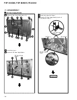
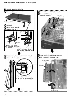
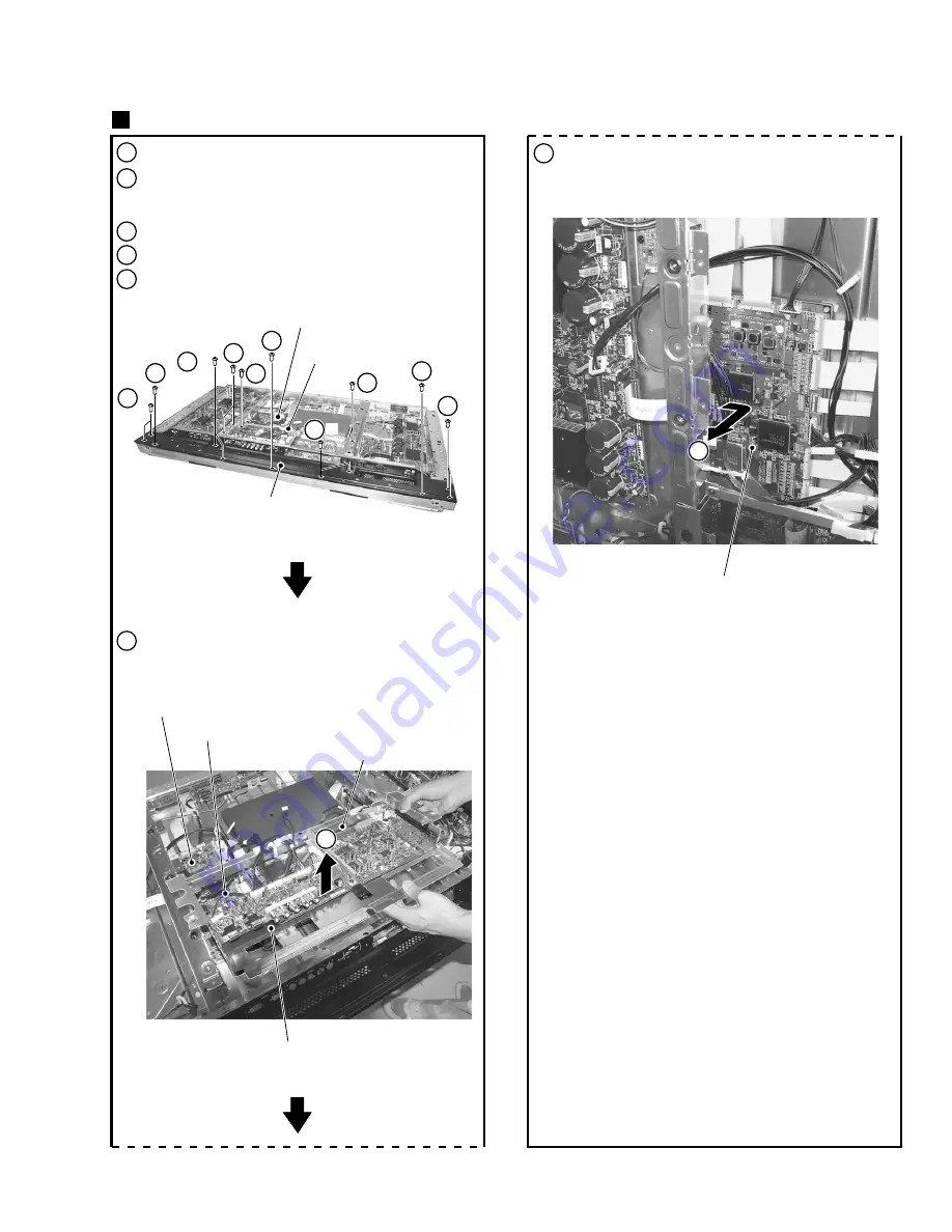
Remove the Rear Case (50M). (Screws
×
20)
3
Remove the Terminal Panel M. (Screws
×
11)
6
7
4
Remove a screw of earth block.
5
Remove the RGB Base. (Screws
×
4)
7
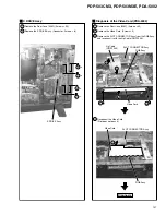
Remove the DIGITAL VIDEO Assy.
(Connector, Circuit Board Spacer
×
6)
6
Remove connectors and binders,
and remove the RGB Base with PCB Assys.
2
Remove the SW Power Supply Module.
(Connector, Screws
×
4)
DIGITAL VIDEO Assy
RGB Base
SLOT CONNECTOR
Assy
DIGITAL VIDEO Assy
RGB Assy
DIGITAL VIDEO Assy
3
3
×
2
3
4
×
2
5
×
2
3
×
2
3
3
×
2
5
×
2
3
Terminal Panel M
RGB Base
DIGITAL VIDEO Assy
Содержание PDA-5002
Страница 5: ...5 PDP 503CMX PDP 503MXE PDA 5002 ...
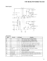
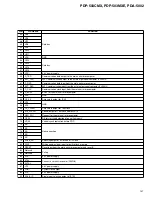
Страница 143: ...PDP 503CMX PDP 503MXE PDA 5002 143 Block Diagram Pin Function ...
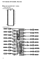
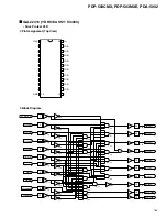
Страница 166: ...PDP 503CMX PDP 503MXE PDA 5002 166 Pin Assignment Top View CXA3516R RGB ASSY IC4603 AD PLL IC ...
Страница 167: ...PDP 503CMX PDP 503MXE PDA 5002 167 Block Diagram ...
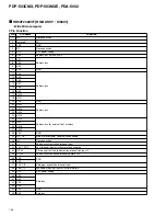
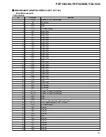
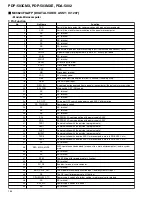
Страница 168: ...PDP 503CMX PDP 503MXE PDA 5002 168 Pin Function ...
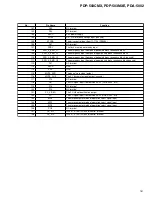
Страница 169: ...PDP 503CMX PDP 503MXE PDA 5002 169 ...
Страница 170: ...PDP 503CMX PDP 503MXE PDA 5002 170 ...


