X-HX5000, X-HX3000, X-HX2000
46
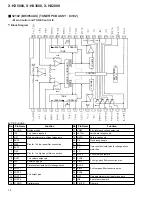
No.
Pin Name
I/O
Function
1
PE2/INT2
I
Port (E) / External interrupt request input
2
PE3/INT3/NMI
I
Port (E) / External interrupt request input / Nonmaskable interrupt input
3
PE4/RMC
I
Port (E) / Remote control reception circuit input
4
PE5/PWM
O
Port (E) / 14 bit PWM output
5
PE6/TO/ADJ
O
Port (E) / 16 bit timer/Rectangle waveform output of counter (duty 50% output) /32 kHz oscillation frequency
6
PB0/CINT
I/O
8 bit input/output port (port B) / 16 bit timer / External capture input of counter
7
PB1/CS0
I/O
8 bit input/output port (port B) / Chip select input of serial interface (CH0)
8
PB2/SCK0
I/O
8 bit input/output port (port B) / serial interface (CH0) input/output
9
PB3/SI0
I/O
8 bit input/output port (port B) / serial data (CH0) input
10
PB4/SO0
I/O
8 bit input/output port (port B) / serial data (CH0) output
11
PB5/SCK1
I/O
8 bit input/output port (port B) / serial clock (CH1) input/output
12
PB6/SI1
I/O
8 bit input/output port (port B) / serial data (CH1) input
13
PB7/SO1
I/O
8 bit input/output port (port B) / serial data (CH1) output
14
PC0
I/O
8 bit input/output port (port C)
15
PC1
16
PC2
17
PC3
18
PC4
19
PC5
20
PC6
21
PC7
22
PH0
I/O
8 bit input/output port (port H)
23
PH1
24
PH2
25
PH3
26
PH4
27
PH5
28
PH6
29
PH7
30
PA0/AN0
I/O
8 bit input/output port (port A) / Analog input to A/D converter
31
PA1/AN1
32
PA2/AN2
33
PA3/AN3
34
PA4/AN4
35
PA5/AN5
36
PA6/AN6
37
PA7/AN7
38
RST
I
System reset of "L" level active
39
EXTAL1
I
Crystal connection pin for system clock oscillation When apply a clock from the external, input to EXTAL1 pin
and input the reverse clock to XTAL1 pin.System clock oscillation use for normal operation mode (Max. 10MHz).
40
XTAL1
−
41
VSS
−
GND pin
42
XTAL2
−
Crystal connection pin for system clock oscillation When apply a clock from the external, input to EXTAL2 pin
and input the reverse clock to XTAL2 pin.System clock oscillation use for sub-clock mode (Typ. 500kHz).
43
EXTAL2
I
44
AVREF
−
Reference voltage input of A/D converter
45
AVSS
−
GND pin of A/D converter
46
VL
O
Control pin for cutoff the current which flows to the bias resistor for external LCD at standby.
47
VLC3
−
Bias power supply pin for LCD
48
VLC2
−
49
VLC1
−
50
COM0
O
Common signal output pin for LCD
•
Pin Function


