MJ-D508
43
Step No.
Operation Keys and Operation Method
FL Display
Status
Remarks
1
Power ON while holding the ENTER key and the
EJECT
Test mode
PLAY key depressed.
2
Press the NAME CLIP key.
TEMP
The microcomputer starts measuring.
: Measuring
value
3
When
is 80 or more at this time, the adjustment
End
is OK (step 4 and following can be omitted).
: Set value
When
is 80 (not passed)
TEMP
8 0
80 is the default value (unadjusted).
4
Measure the ambient temperature T (
°
C) andcheck
hat the measuring value (
) is within the standard
in regard to the microcomputer set value (
).
Note: When the indication of the measuring value
(
) is not stable, and the ambient temperature
T (
°
C) is 25
°
C or less, set to the lower value.
When the ambient temperature is over 25
°
C, set to
the higher value.
5
Change
with the DAC MODE key (UP) and the
TEMP 7B 7B
INPUT SELECTOR key (DOWN).
6
Press the EDIT/NO key.
No Disc
Writing to EEPROM is made and
return is made automatically from
test mode to normal mode.
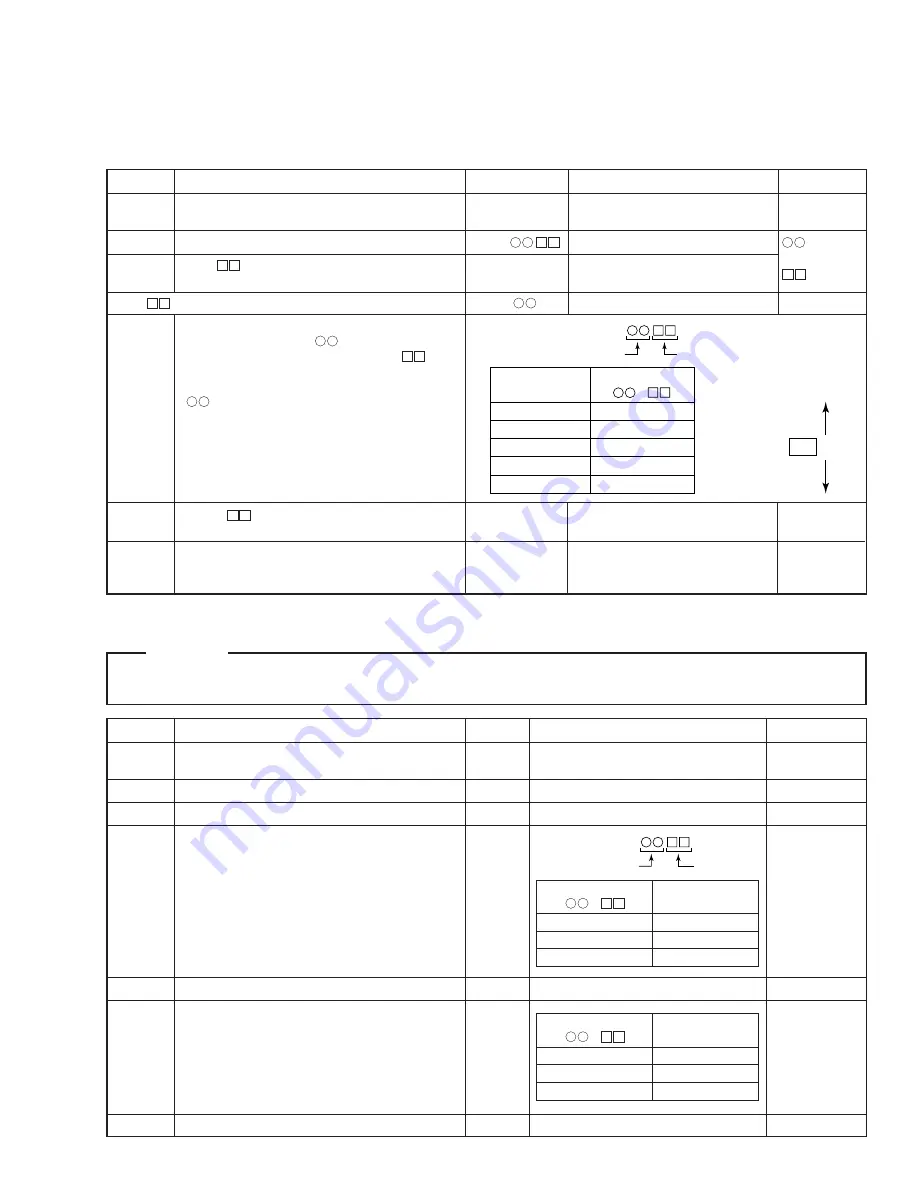
6.2.2 Test Mode 2 (MD Mechanism Assy Adjustment, Check)
Step No.
Operation Keys and Operation Method
FL Display
Status
Remarks
1
Power ON while holding the ENTER key and the
EJECT
Test mode
Laser Wavelength:
PLAY key depressed.
780 nm
2
Press the NAME key.
ppw
PLAY power output status
3
Measure the laser power with an optical power meter.
ppw
4
At this time, check that the measuring value (PLAY
ppw
May be omitted.
power) meets the standard value of the table on the
right.
Note: When the standard value on the right is applied,
the numerical value immediately after entry into test
mode 2 shall be taken as the standard.
5
Press the NAME key.
rpw
REC power output status
6
At this time, check that the measuring value (REC
rpw
power) meets the standard value of the table on the
right.
7
Press the STOP key.
The LD goes out.
1
Temperature Check (Please perform this check soon after the power has been switched on.)
2
Laser Power Check
Note: When IC101 (RF-AMP), IC104 (mechanical controller) or IC110 (EEPROM) has been exchanged or when a correction changing
VD+3 has been made, be sure to correctly perform all steps up to step 6.
TEMP
µ
-com Measuring value
11.6 to 16.9
+1 to +3
17.0 to 22.3
0 to +2
22.4 to 27.6
–1 to +1
27.7 to 33.0
0 to –2
33.1 to 38.4
–1 to –3
79
7A
7B
7C
7D
hex=
( – )
Room Temperature
[ T (
°
C) ]
µ
-com Set value
When the
microcomputer
value is
+
–
hex =
Standard Value
(
–
)
(mW)
+02 to +04
0.69±0.12
–01 to +01
0.67±0.1
–02 to –04
0.63±0.1
TEMP
µ
-com
Measuring value
µ
-com
Set value
hex =
Standard Value
(
–
)
(mW)
+02 to +04
6.18±0.93
–01 to +01
5.79±0.87
–02 to –04
5.47±0.82
CAUTION
• Never look directly at the objective lens. Rec power (rpw) is than ten times greater than Playback power (ppw) is released.
• Never turn the pickup volume and be careful of touch it. Laser power of pickup has been adjusted in the factory shipping.
Содержание MJ-D508
Страница 20: ...MJ D508 20 A B C D 1 2 3 4 1 2 3 4 3 4 MAIN UNIT ASSY 2 2 C E CN701 13 14 16 15 12 17 ...
Страница 33: ...MJ D508 33 A B C D 5 6 7 8 5 6 7 8 Q304 POWER SUPPLY UNIT ASSY D MAIN UNIT ASSY C SIDE B ...
Страница 34: ...MJ D508 34 A B C D 1 2 3 4 1 2 3 4 DISPLAY UNIT ASSY E 4 4 DISPLAY UNIT ASSY ...
Страница 35: ...MJ D508 35 A B C D 5 6 7 8 5 6 7 8 C CN404 SIDE A SIDE B RNP1732 C ...
Страница 62: ...MJ D508 62 PDG240A IC701 DISPLAY UNIT ASSY System Control µ com Block Diagram Pin Assignment Top view ...
Страница 67: ...MJ D508 67 ...


