En(4/10)
Setting the unit
What’s what
Top side
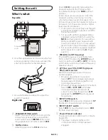
1 2 3 4
1 2 3 4
5
6
7
Top panel
cover
Use the supplied wrench to remove the four
screws and detach the top panel cover. Be
sure not to lose the removed screws.
1
2
Use a flathead screwdriver to adjust the
switch if needed.
Right side
1
SPEAKER SETTING switch
Switch the output power according to the
connected speaker. When a subwoofer
is connected, select
MONO
. When a full
range speaker is connected, select
2CH
.
2
GAIN volume
Adjusting gain volume
CH A
(channel
A) and
CH B
(channel B) helps align the
headunit output to the Pioneer ampli-
fier. Default setting is the
NOR
(normal)
position.
If the output remains low even when the
headunit volume is turned up, turn the
volume to a lower level (clockwise). If dis-
tortion occurs when the headunit volume is
turned up, turn these volumes to a higher
level (counterclockwise).
If using only one input plug, set the gain
volumes for speaker outputs A and B to
the same position.
For use with an RCA equipped stereo
(standard output of 500 mV), set to the
NOR
(normal) position. For use with an
RCA equipped Pioneer headunit with
maximum output of 4 V or more, adjust
level to match that of the stereo output.
For use with an RCA equipped headunit
with output of 4 V, set to the
H
(High)
position.
3
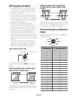
FREQ (Hz) (cutoff frequency)
The cutoff frequency is selectable from
50 Hz to 500 Hz when the
LPF/HPF
select
switch is set to either
LPF
or
HPF
. For more
information, refer to
the Precise Frequency
Selection Chart.
4
+/%ÄKNVO@RRÄ×KSDQ'/%ÄGHFGO@RRÄ
×KSDQÄRDKDBSÄRVHSBG
Switch the settings based on the con-
nected speaker.
When a subwoofer is connected:
Select
LPF
. This eliminates high range
frequencies and limits output to only
low range frequencies.
When a full range speaker is connected:
Select
HPF
or
OFF
.
HPF
eliminates
low range frequencies and limits
output to only high frequencies.
OFF
bypasses the
LPF/HPF
and outputs all
frequencies.
5
INPUT SENS switch
Select
RCA
for RCA level input signals or
SP
(Speaker) for Speaker level input signals.
6
INPUT SELECT switch
Select
2CH
for two-channel input or
4CH
for four–channel input.
7
Power/Protect indicator
The power indicator lights blue to indicate
power ON.
The power indicator lights red to
indicate protection mode has been
engaged.

